Arrangement to measure the deflection of an object

Inactive Publication Date: 2012-08-09
SIEMENS AG
View PDF5 Cites 4 Cited by
  • Summary
  • Abstract
  • Description
  • Claims
  • Application Information

AI Technical Summary

Benefits of technology

[0009]It is therefore the aim of the invention to provide an improved arrangement and method t

Problems solved by technology

The installation of gauges and the installation of their electrical cabling needed is expensive, especially asides a wind turbine which is in o

Method used


Image

  • Arrangement to measure the deflection of an object
  • Arrangement to measure the deflection of an object
  • Arrangement to measure the deflection of an object

Examples


Embodiment Construction

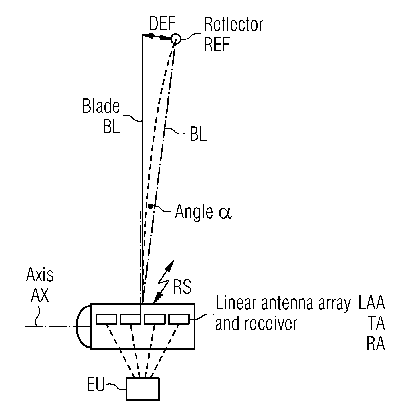
[0037]FIG. 1 shows one preferred arrangement according to the invention.

[0038]The deflection DEF or bending of a wind turbine blade BL needs to be measured.

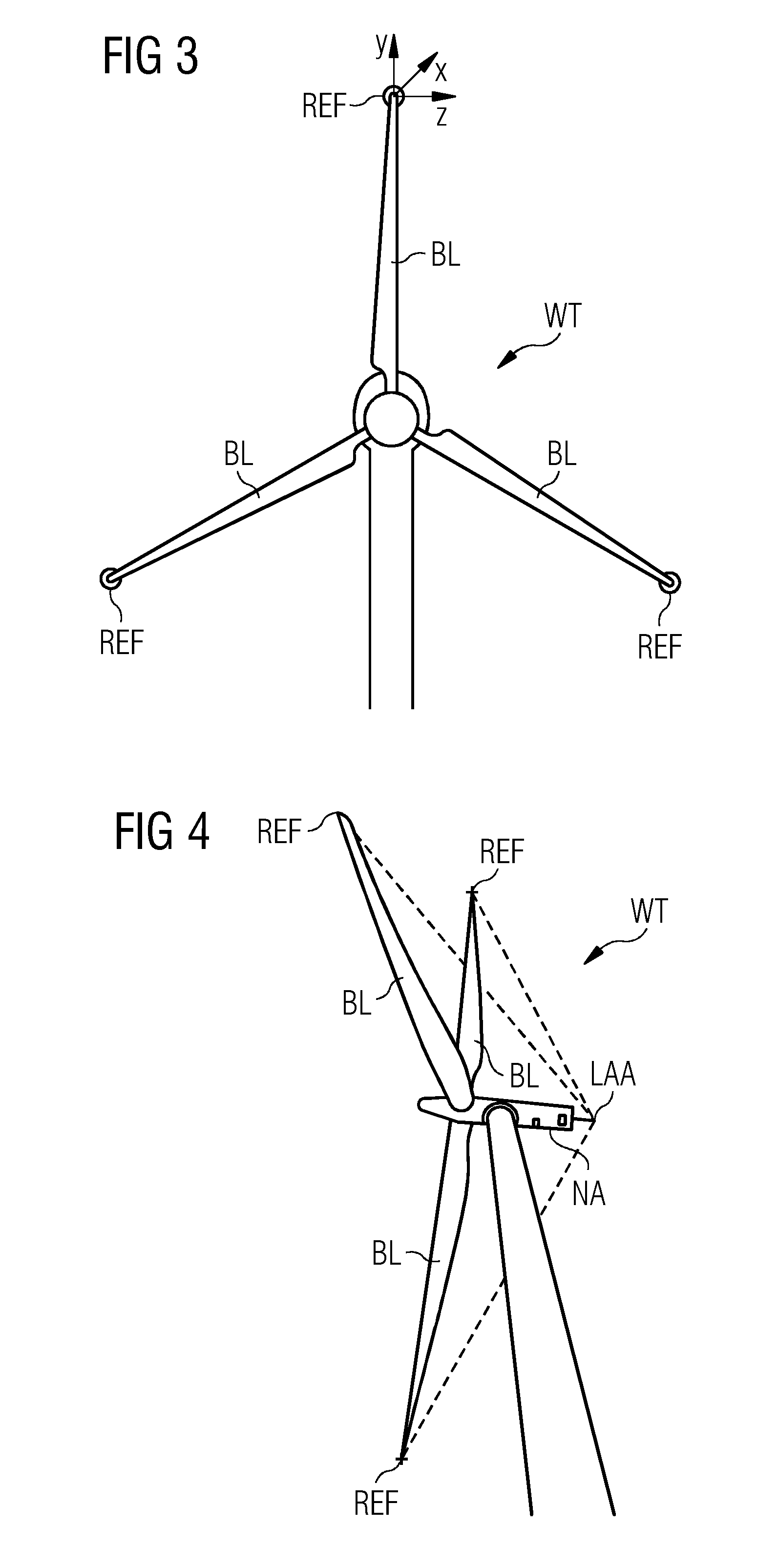
[0039]A reflector REF is arranged asides a first end of the blade BL.

[0040]An antenna-system LAA contains at least one transmit antenna TA and—as a plurality of receive antennas RA, for example four receive antennas RA as illustrated.

[0041]The antenna system LAA is arranged asides the nacelle of the wind turbine and close to the second end of the blade BL.

[0042]The antenna system LAA is part of an active radar system.

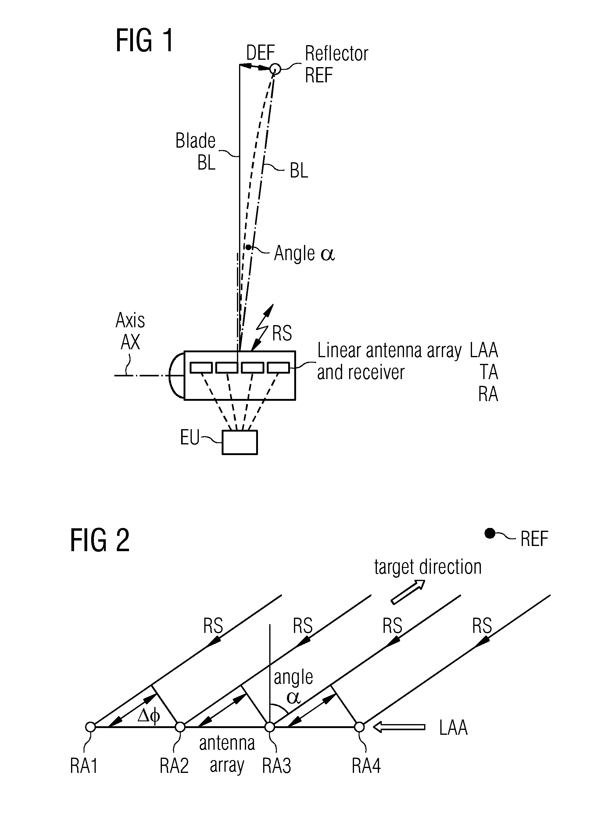
[0043]The four receive antennas RA are arranged as “linear antenna array”.

[0044]The reflector REF and the antenna-system LAA are coupled by a radio signal RS, which is sent from the transmit antenna TA via the reflector REF towards the receive antennas RA.

[0045]The receive antennas RA are connected with an evaluation unit EU, which is prepared to measure the deflection DEF between the first end of the blade BL and th...


PUM


Abstract

A reflector is arranged at a first position, which is assigned to a first end of the object. An antenna-system is arranged at a second position, which is assigned to a second end of the object. The antenna system contains a transmit antenna and a receive antenna, while the reflector and the antenna-system are coupled by a radio signal. The radio signal is sent from the transmit antenna via the reflector towards the receive antenna. The receive antenna is connected with an evaluation unit, which is prepared to measure the deflection between the first end of the object and the second end of the object based on the received radio signal.

Description

CROSS REFERENCE TO RELATED APPLICATIONS[0001]This application claims priority of European Patent Office application No. 11153559.7 EP filed Feb. 7, 2011. All of the applications are incorporated by reference herein in their entirety.FIELD OF INVENTION[0002]The invention relates to an arrangement to measure the deflection or bending of an object, preferably to measure the deflection or bending of a wind-turbine blade.BACKGROUND OF INVENTION[0003]Blades of modern wind turbines are quite long—they are up to 45 meters long or even more. Thus their shape and their characteristics need to be optimized, especially to prevent that turning blades hit the tower while the wind turbine is in operation.[0004]Especially the deflection or bending of the blade near its tip-end needs to be known to prevent those damages.[0005]It is known to attach strain gauges on the blade-surface. They are mainly used for test purposes to gather a certain knowledge about the blade when it is stressed.[0006]The ins...

Claims


Application Information

Patent Timeline
IPC IPC(8): G01S13/42
CPCG01B15/06G01S3/48G01S13/88G01S13/75G01S13/42
Inventor ANDERSEN, JIMMIEGEDAL, PERSTIESDAL, HENRIKZIROFF, ANDREAS
Owner SIEMENS AG
Why Eureka
Try Eureka