Inkjet recording device

a recording device and inkjet technology, applied in printing, other printing devices, etc., can solve the problems of ink splashing on the surrounding of the gutter

Inactive Publication Date: 2012-08-09
HITACHI IND EQUIP SYST CO LTD
View PDF1 Cites 8 Cited by
  • Summary
  • Abstract
  • Description
  • Claims
  • Application Information

AI Technical Summary

Problems solved by technology

Accordingly, after the recovery of the ink is stopped, feeding of the solvent gas to the gutter is continued, and the ink remaining in the gutter is pushed out from the gutter by the solvent gas, which then fouls the surrounding of the gutter with the ink.

Method used


Image

  • Inkjet recording device
  • Inkjet recording device
  • Inkjet recording device

Examples


example 1

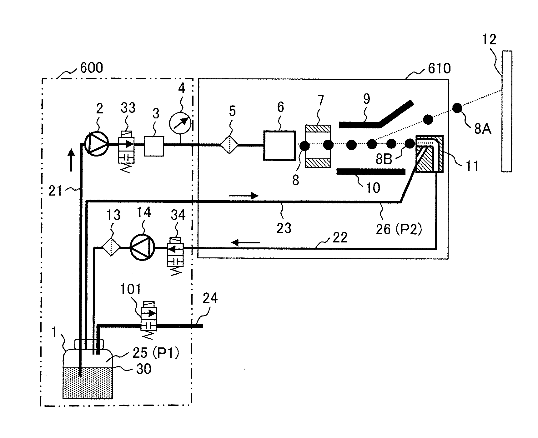
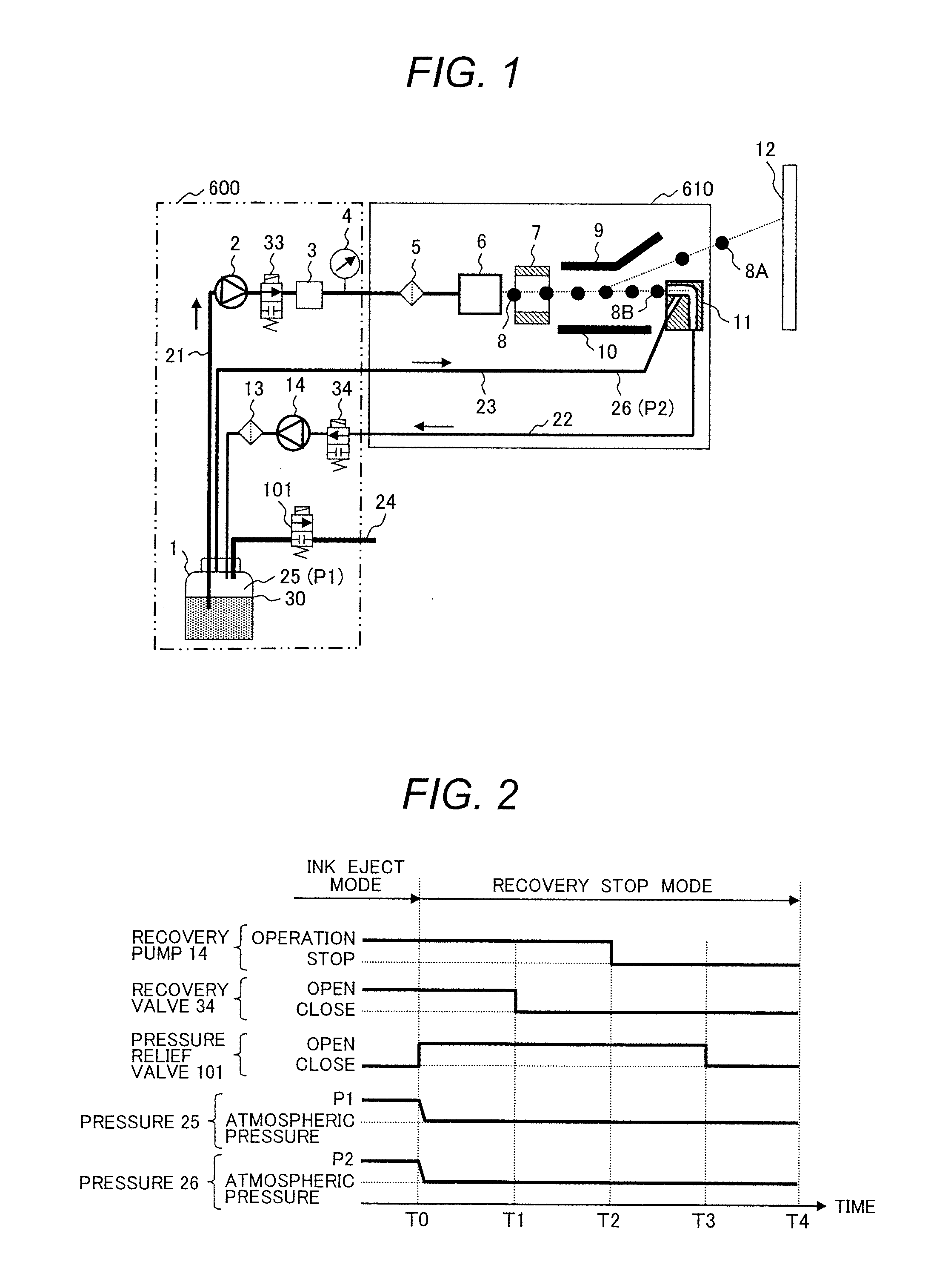
[0029]First, FIG. 6 shows a general view of a main body of the inkjet recording device.

[0030]The inkjet recording device is composed of a main body 600 which accommodates a control system and a circulation system, a print head 610 which ejects ink particles, and a cable 620 which connects the main body 600 and the print head 610. The length of the cable 620 is 4 m. The main body 600 has a touch panel type liquid crystal panel 630 which enables the user to input a print content, printing specification and other information, and is capable of displaying control details and operational status of the device. A nozzle for producing the ink particles and electrodes for electrifying and deflecting the ink particles are contained within the print head 610. The print head is covered by a cover made of a stainless steel. An opening portion 640 through which the ink particles can pass is provided at the tip of the print head 610. A lid 670 which can be opened and closed in is provided at a low...

example 2

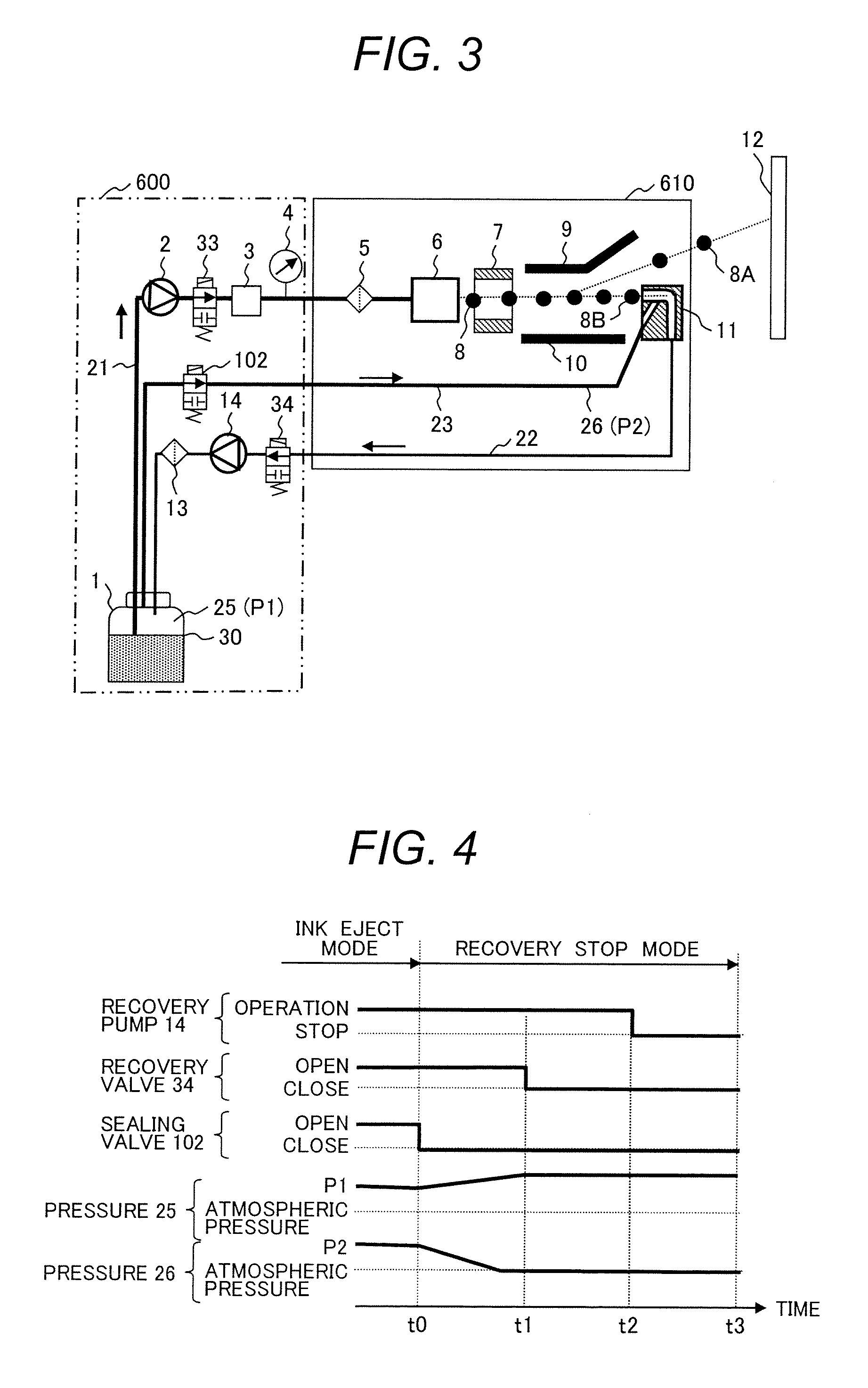
[0061]FIG. 3 is a configuration of a second device to obtain the effects of the invention of the inkjet recording device of the present invention without using a pressure relief line 24 in Example 1.

[0062]A configuration which is different from that of Example 1 will be described below.

[0063]A sealing valve 102 which is capable of opening and closing the exhaust circulation line is provided on the exhaust circulation line 22 which connects the ink tank 1 and the gutter 11. The sealing valve 102 is an electromagnetic two-way valve, which can bring the ink tank 1 and gutter 11 into communication and feed the solvent gas from the ink tank 1 to the gutter 11 in an open state, but cannot feed the solvent gas from the ink tank 1 to the gutter 11 in a closed state.

[0064]It should be noted that sealing valve 102 may be a flow rate adjustment valve which has a function of adjusting the flow rate.

[0065]Herein, the flow of the solvent gas in an operation mode will be described with reference t...


PUM


Abstract

Leakage of an ink remaining in a gutter or the like is prevented. An inkjet recording device includes an ink tank for retaining an ink, a nozzle for discharging the ink as ink particles to print on a printing object, an ink supply unit for feeding the ink from the ink tank to the nozzle, a gutter for recovering the ink particles which are not used in printing in the ink tank among the ink particles discharged from the nozzle, an ink recovery line for returning the ink particles recovered in this gutter to the ink tank, and an ink recovery unit disposed on this ink recovery line for recovering the ink in the ink tank. The inkjet recording device has a gas-liquid separation unit for separating a gas returned along with the ink particles through the ink recovery line, a gas supply line for feeding the gas to the gutter, and an atmosphere relief line for releasing the gas from the gas-liquid separation unit to the outside.

Description

RELATED APPLICATIONS[0001]This application is the U.S. National Phase under 35 U.S.C. §371 of International Application No. PCT / JP2010 / 001164, filed on Feb. 23, 2010, which in turn claims the benefit of Japanese Application No. 2009-150681, filed on Jun. 25, 2009, the disclosures of which Applications are incorporated by reference herein.TECHNICAL FIELD[0002]The present invention relates to an inkjet recording device.BACKGROUND ART[0003]In an inkjet recording device which prints out by ejecting an ink from a nozzle, it is necessary to supply a solvent for volatilized and lost ink to maintain the properties of the ink when the ink discharged from the nozzle once is recovered and reused.[0004]Patent document 1(Japanese Unexamined Patent Publication No. 60-011364) discloses an inkjet recording device for the purpose of providing an ink circulation system with less ink deterioration which suppresses vaporization of ink solvent components, the inkjet recording device being characterized ...

Claims


Application Information

Patent Timeline
Patent Type & Authority Applications(United States)
IPC IPC(8): B41J2/185B41J2/19B41J29/38
CPCB41J2/175B41J2/185B41J2/18
Inventor INOUE, TOMOHIROMIYAO, AKIRANAGAMINE, TOSHIHIDE
Owner HITACHI IND EQUIP SYST CO LTD
Why Eureka
Try Eureka