Information storage device, removable device, developer container, and image forming apparatus

a technology of information storage device and developer container, which is applied in the direction of digital output to print units, visual presentation using printers, instruments, etc., can solve the problems of misalignment of contact sections of conventional contact information storage device and electrical damage of conventional contact type information storage devi

Active Publication Date: 2012-08-09
RICOH KK
View PDF2 Cites 71 Cited by
  • Summary
  • Abstract
  • Description
  • Claims
  • Application Information

AI Technical Summary

Benefits of technology

[0012]There is a need to solve the first problem described above and provides an information storage device, a removable device, a developer container, and an image forming apparatus in which electrical damage is difficult to occur in the information storage device even when the contact-type information storage device is installed in the removable device removably installed in the image forming apparatus body.
[0014]There is a need to solve the second problem described above and provides a removable device, a developer container, and an image forming apparatus in which a contact failure caused by a positioning failure with the body side terminal of the connector of the image forming apparatus body is difficult to occur even when the contact-type information storage device is installed in the removable device removably installed in the image forming apparatus body.
[0008]Further, a feeding opening for allowing the stored toner to flow out to the outside is installed in the developer container. The opening needs remain closed until it is loaded onto a developing device so as to prevent the toner from being scattered or leaking.

Problems solved by technology

However, the conventional techniques described above have the following problems.
As a first problem, the conventional contact-type information storage device may electrically get damaged since an electric circuit of the information storage device is not sufficiently earthed and so becomes an electrically floating state when the removable device is attached to or removed from the device body.
As a second problem, in the conventional contact-type information storage device, there may occur a problem in that contact sections thereof are misaligned (a contact failure) due to wrong positioning of the terminal (metal pad) installed in the information storage device and the terminal of the image forming apparatus body.
Particularly, when the terminal of the information storage device is small, the problem becomes important.
Improving a filter function so as to cope with using the toner may increase the material or processing cost.
This tendency may be difficult to go along with movement of the shutter, and a sealing characteristic may get worse.

Method used


Image

  • Information storage device, removable device, developer container, and image forming apparatus
  • Information storage device, removable device, developer container, and image forming apparatus
  • Information storage device, removable device, developer container, and image forming apparatus

Examples


first embodiment

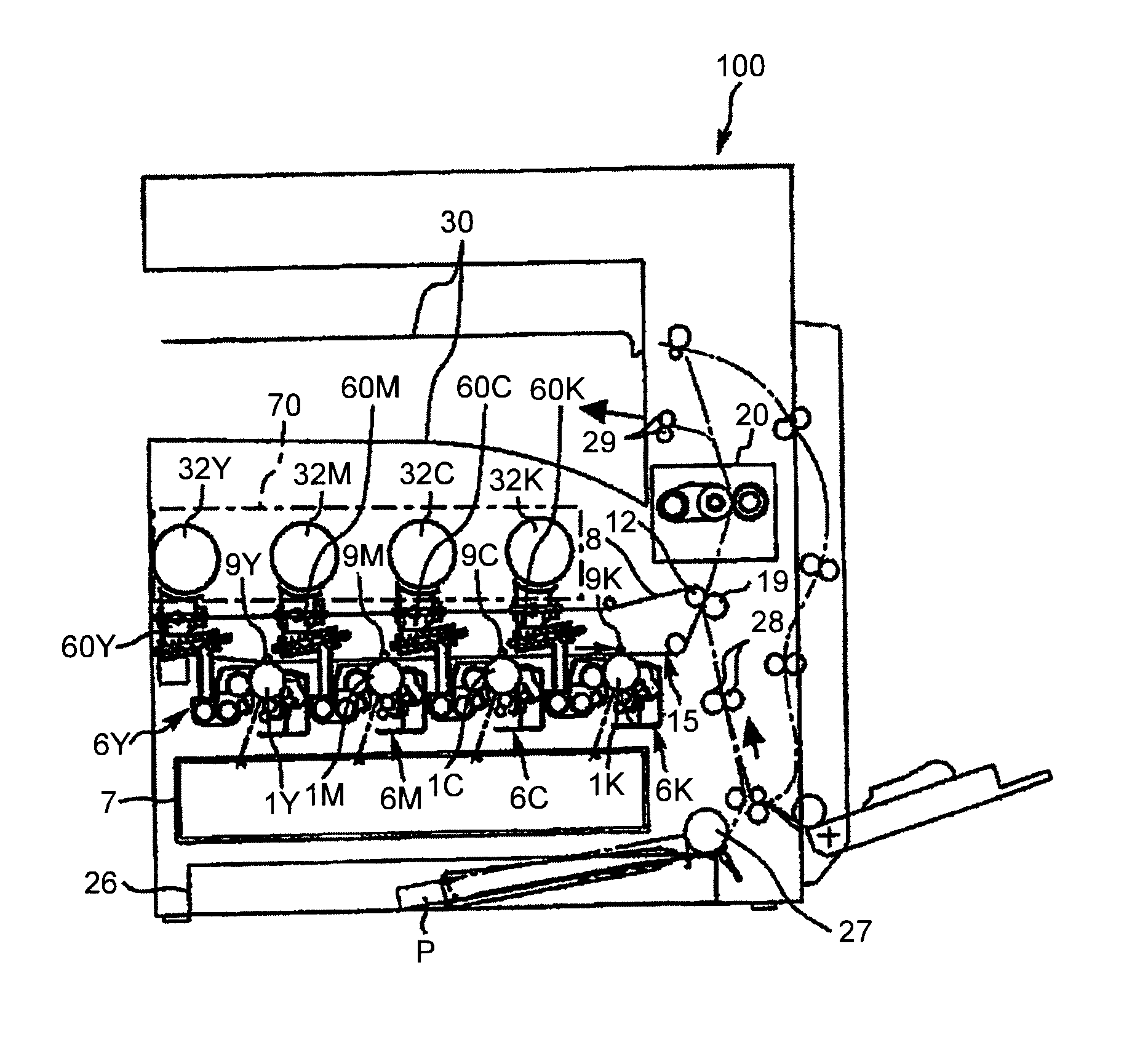
[0113]A first embodiment of the present invention will be described in detail with reference to FIGS. 1 to 30.

[0114]First, a configuration and operation of the entire image forming apparatus will be described.

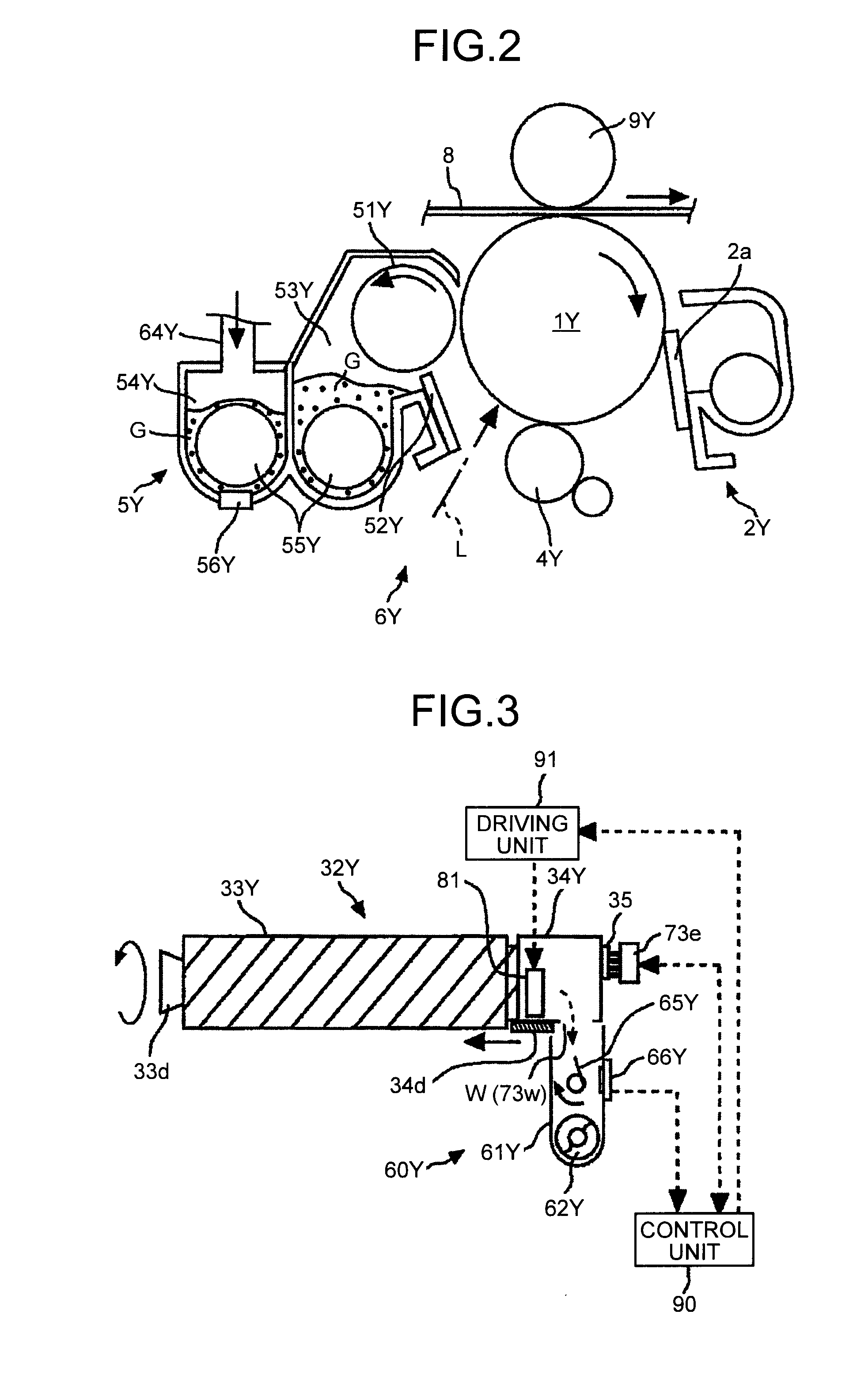
[0115]As illustrated in FIG. 1, in a toner container storage unit 70 above an image forming apparatus body 100, toner containers 32Y, 32M, 32C, and 32K (developer containers) are removably (replaceably) installed as four removable devices corresponding to respective colors (yellow, magenta, cyan, and black) (also see FIGS. 3 to 5).

[0116]An intermediate transfer unit 15 is disposed below the toner container storage unit 70. Image forming units 6Y, 6M, 6C, and 6K corresponding to respective colors (yellow, magenta, cyan, and black) are disposed in line to face an intermediate transfer belt 8 of the intermediate transfer unit 15.

[0117]Toner feeding devices 60Y, 60M, 60C, and 60K are disposed below the toner containers 32Y, 32M, 32C, and 32K as the removable devices (developer cont...

second embodiment

[0266]A second embodiment of the present invention will be described in detail with reference to FIGS. 31 to 33.

[0267]FIG. 31 is a schematic cross sectional view illustrating a toner container 232Y according to the present second embodiment. FIG. 32 is a back view illustrating a cap section 234Y of a toner container 232Y. FIG. 33 is a perspective view illustrating a holding cover 234k8 that is fitted into a holding member 234k.

[0268]The toner container 232Y according to the present second embodiment is different from the first embodiment in configuration of the holding member 234k in a holding mechanism for holding the information storage device.

[0269]Similarly to the first embodiment, the toner container 232Y according to the present second embodiment includes the container body 33Y and a cap section 234Y. The ID chip 35 as the information storage device is removably installed in the cap section 234Y.

[0270]In the cap section 234Y according to the present second embodiment, the hol...

third embodiment

[0276]A third embodiment of the present invention will be described in detail with reference to FIG. 34.

[0277]FIG. 34 is a schematic view illustrating a state in which the information storage device 35 of a toner container 332Y according to the present third embodiment is set to the connector 73e of the cap receiving section 73. FIG. 34 is a view corresponding to FIG. 27 in the first embodiment.

[0278]The present third embodiment is different from the first embodiment in that a cushion material 334k10 is installed inside the holding member 34k and a configuration of a wall section 373g of a cap receiving section 373 is different.

[0279]Similarly to the above embodiments, a toner container 332Y according to the present third embodiment includes a container body 33Y and the cap section 34Y. The ID chip 35 as the information storage device is removably installed in the cap section 34Y. Further, the ID chip 35 is held in the holding member 34k to be movable in the XZ plane.

[0280]In the pr...


PUM

PropertyMeasurementUnit
thicknessaaaaaaaaaa
thicknessaaaaaaaaaa
sizeaaaaaaaaaa

Abstract

An information storage device installed in a removable device configured to be removably installed in an image forming apparatus body, includes: an information storage unit that stores information communicated between the image forming apparatus body and the removable device; a terminal that comes in contact with a body side terminal; and a substrate that holds the information storage unit and the terminal and includes a hole configured to be engaged with a protruding section installed in the image forming apparatus body. The terminal includes a plurality of terminals each including one of a plurality of metallic plates arranged in a transverse direction thereof. An earth terminal, which comes in contact with a body side earth terminal formed in the protruding section, is formed in the hole. The hole is disposed at a position sandwiched between two metallic plates among the plurality of metallic plates.

Description

CROSS-REFERENCE TO RELATED APPLICATIONS[0001]This application is a continuation of PCT international application Ser. No. PCT / JP2011 / 063993 filed on Jun. 13, 2011 which designates the United States, and which claims the benefit of priority from Japanese Patent Application No. 2010-134560, filed on Jun. 11, 2010, Japanese Patent Application No. 2011-062216, filed on Mar. 22, 2011, Japanese Patent Application No. 2011-062283, filed on Mar. 22, 2011, Japanese Patent Application No. 2011-084820, filed on Apr. 6, 2011, and Japanese Patent Application No. 2011-087786, filed on Apr. 11, 2011; the entire contents of which are incorporated herein by reference.BACKGROUND OF THE INVENTION[0002]1. Field of the Invention[0003]The present invention relates to an image forming apparatus such as a copying machine, a printer, a facsimile, or a multi-function peripheral (MFP), a removable device and a developer container that are removably installed therein, and an information storage device installe...

Claims


Application Information

Patent Timeline
Patent Type & Authority Applications(United States)
IPC IPC(8): H04N1/60G03G15/06G06K15/02
CPCG03G21/1652Y10T29/49002G03G2215/0697G03G2221/166G03G21/16G03G21/1661G03G21/00G03G15/0865G03G15/5066B41J2/17546G03G15/0863G03G21/1676G03G21/1875G03G2221/1823B41J2/17526G03G15/0872G03G15/0886G03G15/55G03G15/553G03G21/1885G03G21/1842G03G15/00G03G15/50B41J2/1753G03G15/0875G03G15/0891
Inventor TAKAHASHI, YASUFUMIOHYAMA, KUNIHIROYAMANE, MASAYUKIUCHITANI, TAKESHIHAYAKAWA, TADASHITAKAHASHI, TAKUJIOKABE, SHOUJISHINSHI, AKIRAUEDA, YUICHIROTAKAHASHI, MASAKISATOH, YUUKI
Owner RICOH KK
Why Eureka
Try Eureka