Permanent magnet for motor, and method for manufacturing the permanent magnet for motor

a permanent magnet and motor technology, applied in the direction of magnetic circuit rotating parts, magnetic circuit shape/form/construction, magnetic bodies, etc., can solve the problems of increased production steps, difficult to uniformly perform contraction, and sparse and dense magnets

Inactive Publication Date: 2015-07-28
NITTO DENKO CORP +1
View PDF29 Cites 4 Cited by
  • Summary
  • Abstract
  • Description
  • Claims
  • Application Information

AI Technical Summary

Benefits of technology

[0011]The present invention has been made for the purpose of solving the above-mentioned conventional problems, and an object is to provide a permanent magnet for motor, in which the contraction due to sintering becomes uniform and the deformations such as warpage and depressions hardly occur after sintering, and to provide a method for producing such a permanent magnet for motor. Even when the permanent magnet motor with the permanent magnets buried therein is rotated at a high speed, the eddy current to occur inside the permanent magnets may be reduced, and therefore the permanent magnets therein are free from the problems of temperature elevation and coercive force depression. The permanent magnet has made it possible to provide a high-torque small-sized motor.
[0063]According to the permanent magnet for a motor of the above (13), the respective sheet magnets are, after molded, bonded with the resin to be the insulating layer. Therefore, permanent magnets produced under conventional sintering conditions may be bonded with a resin to obtain a simple-structured permanent magnet in which the eddy current to occur inside the magnets may be reduced.

Problems solved by technology

And when the magnet powder having the predetermined porosity is sintered, it is difficult to uniformly perform contraction which occurs at the time of sintering, and deformations such as warpage and depressions occur after sintering.
Further, since pressure unevenness occurs at the time of pressing the magnet powder, sparse and dense of the magnet after sintering are formed to generate strain on a surface of the magnet.
As a result, production steps increase, and there is a possibility of deteriorating qualities of the permanent magnet produced.

Method used


Image

  • Permanent magnet for motor, and method for manufacturing the permanent magnet for motor
  • Permanent magnet for motor, and method for manufacturing the permanent magnet for motor
  • Permanent magnet for motor, and method for manufacturing the permanent magnet for motor

Examples


Embodiment Construction

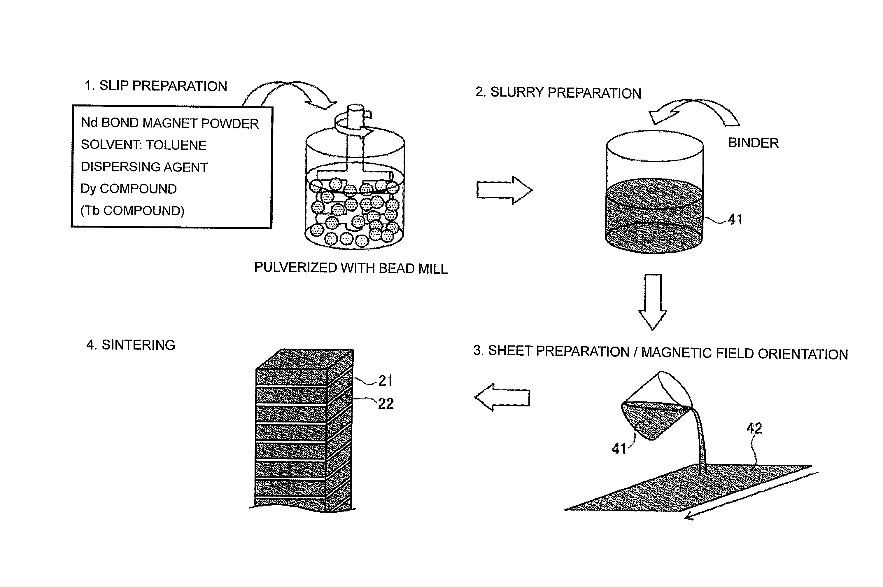
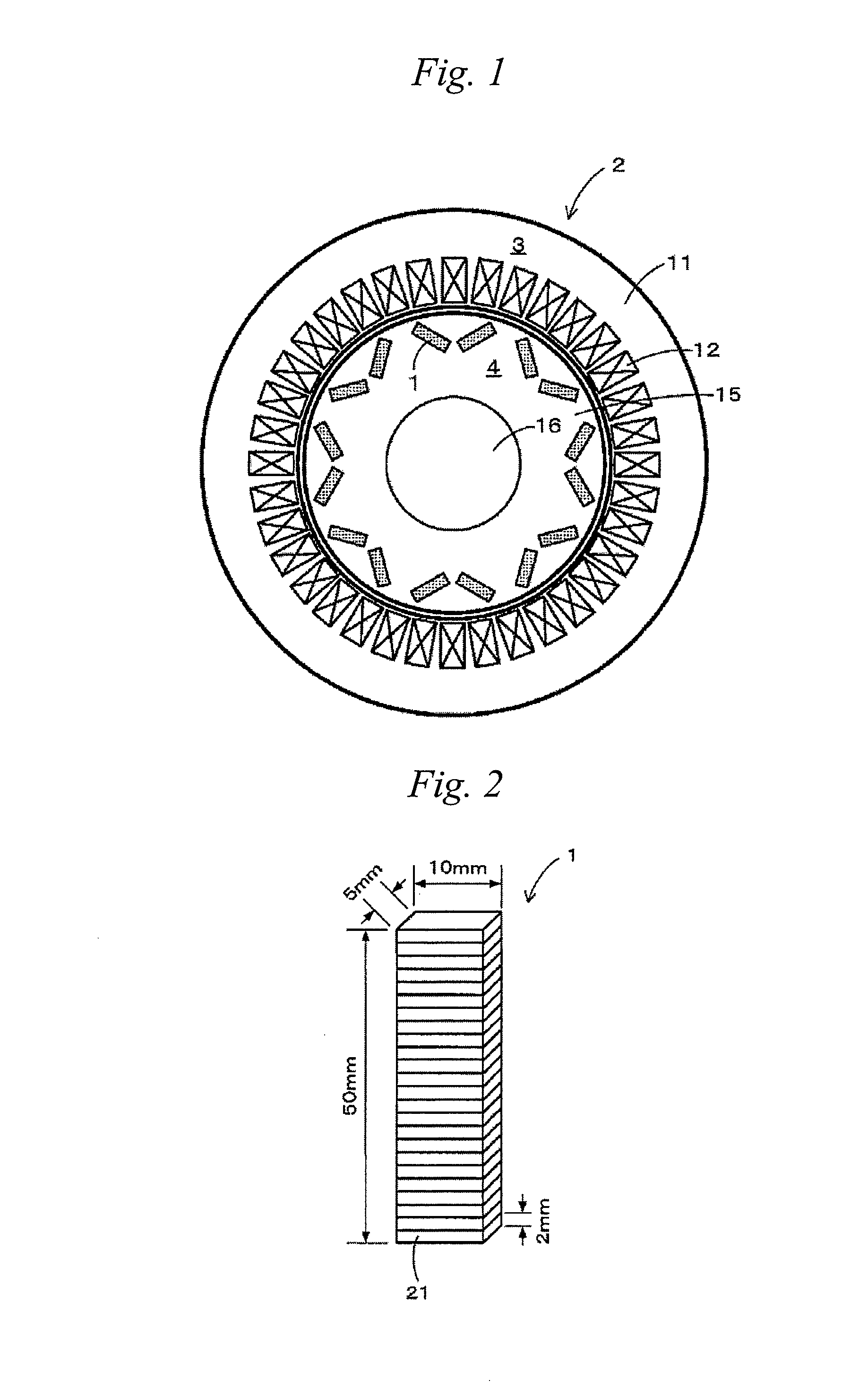
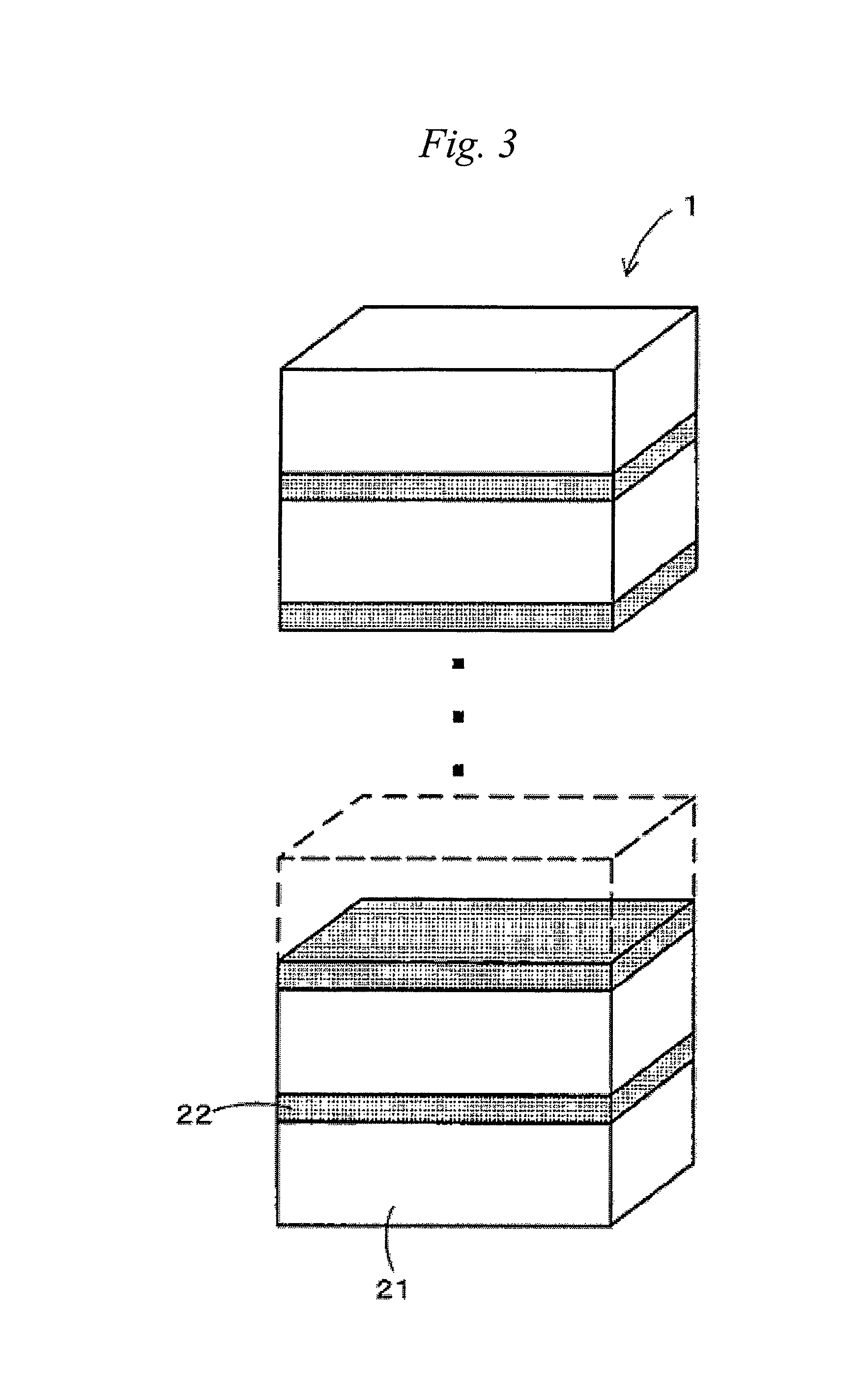
[0079]A specific embodiment of a permanent magnet for motor and a method for producing a permanent magnet for motor according to the invention will be described below with reference to the drawings. First described is the constitution of a permanent magnet motor 2 with permanent magnets 1 of the present embodiment buried therein, with reference to FIG. 1. FIG. 1 is a view showing the internal constitution of a permanent magnet motor 2 according to the present embodiment.

[0080]As shown in FIG. 1, the permanent magnet motor 2 basically includes a stator 3 and a rotor 4 rotatably arranged inside the stator 3.

[0081]First described is the stator 3. The stator 3 includes a stator core 11 and a plurality of stator windings 12 wound around the stator core 11. A predetermined number of stator windings 12 are arranged on the inner peripheral surface of the stator 3 at regular intervals, and when the stator windings 12 are electrically charged, they generate a rotation magnetic field for rotat...


PUM

PropertyMeasurementUnit
thicknessaaaaaaaaaa
sizeaaaaaaaaaa
sizeaaaaaaaaaa

Abstract

A method for producing a permanent magnet for a motor, including a step of producing a slurry of a magnet powder, a step of molding the slurry into a sheet form to prepare green sheets of the magnet powder, and a step of alternately laminating the green sheets of the magnet powder and an insulating layer and sintering the laminated plural layers.

Description

TECHNICAL FIELD[0001]The present invention relates to a permanent magnet for a motor, to be buried in a permanent magnet motor, and relates to a method for producing a permanent magnet for a motor.BACKGROUND ART[0002]In recent years, a reduction in size and weight, an increase in power and an increase in efficiency have been required for permanent magnet motors used in hybrid vehicles, hard disk drives or the like. Such a permanent magnet motor has a configuration in which permanent magnets are buried in the outer periphery of a rotor and coils are arranged in the inner periphery of a stator, for example, as shown in Patent Document 1 (JP-A 2007-306735).[0003]In realizing the reduction in size and weight, the increase in power and the increase in efficiency of the permanent magnet motor, further improvement of the magnetic characteristics is required for the permanent magnets to be buried in the permanent magnet motor. The permanent magnet includes ferrite magnets, Sm—Co-based magne...

Claims


Application Information

Patent Timeline
Patent Type & Authority Patents(United States)
IPC IPC(8): H01F41/02H02K15/03H01F1/04H01F10/12H02K1/27H01F1/057
CPCH01F41/0293H01F1/0577H01F10/126H01F41/0266H02K1/2766H02K15/03H01F1/0572Y10T29/49009H01F1/08H02K1/27H02K15/00H02K21/00
Inventor OZEKI, IZUMIKUME, KATSUYANAKAYAMA, JUNICHIFUKUDA, YUUKIHOSHINO, TOSHINOBUHORIO, TOMOKAZUNAKAMURA, KENJI
Owner NITTO DENKO CORP
Why Eureka
Try Eureka