Battery Charge Protection System

a battery charge protection and battery technology, applied in the field of electronic circuits, can solve the problems of damage to equipment, maintenance requirements, and li-ion battery performance being negatively impacted,

Active Publication Date: 2012-08-09
COBHAM ADVANCED ELECTRONICS SOLUTIONS
View PDF1 Cites 17 Cited by
  • Summary
  • Abstract
  • Description
  • Claims
  • Application Information

AI Technical Summary

Benefits of technology

[0006]Various example embodiments of the present disclosure may be directed to a system and electronic apparatuses for maintaining battery operation. A system may comprise a battery comprising one or more cells, an energy source, a load and a circuit coupled to at least the battery, the energy source and the load. The circuit may comprise elements configured to measure the charge of each of the one or more cells. If it is determined that the charge of any of the one or more cells is at or above a predetermined charg

Problems solved by technology

However, while emerging battery technologies like Li-ion compositions may be able to provide strong performance, these benefits come with some maintenance requirements.
For example, Li-ion battery performance may be negatively impacted by conditions where the cells in a battery are unbalanced (e.g., one cell in a battery has a higher charge than another cell), as well as the cells being undercharged or overcharged.
Undercharging Li-ion batteries can result in electrical shorts that cause the cells to discharge to a state where it is possible the battery cannot recover (e.g., the cells will not recharge).
In more extreme cases, overcharging batteries can result in failures including white-hot flames or explosions that can damage equipment.
Even in view of these care requirements and potential failures, safeguards may be built into commercial apparatuses to provide protection that, even if a failure occurs, may simply lead

Method used


Image

  • Battery Charge Protection System
  • Battery Charge Protection System
  • Battery Charge Protection System

Examples


Embodiment Construction

[0018]While illustrative implementations of one or more embodiments of the present invention are provided below, various changes can be made therein without departing from the spirit and scope of the invention, as described in the appended claims.

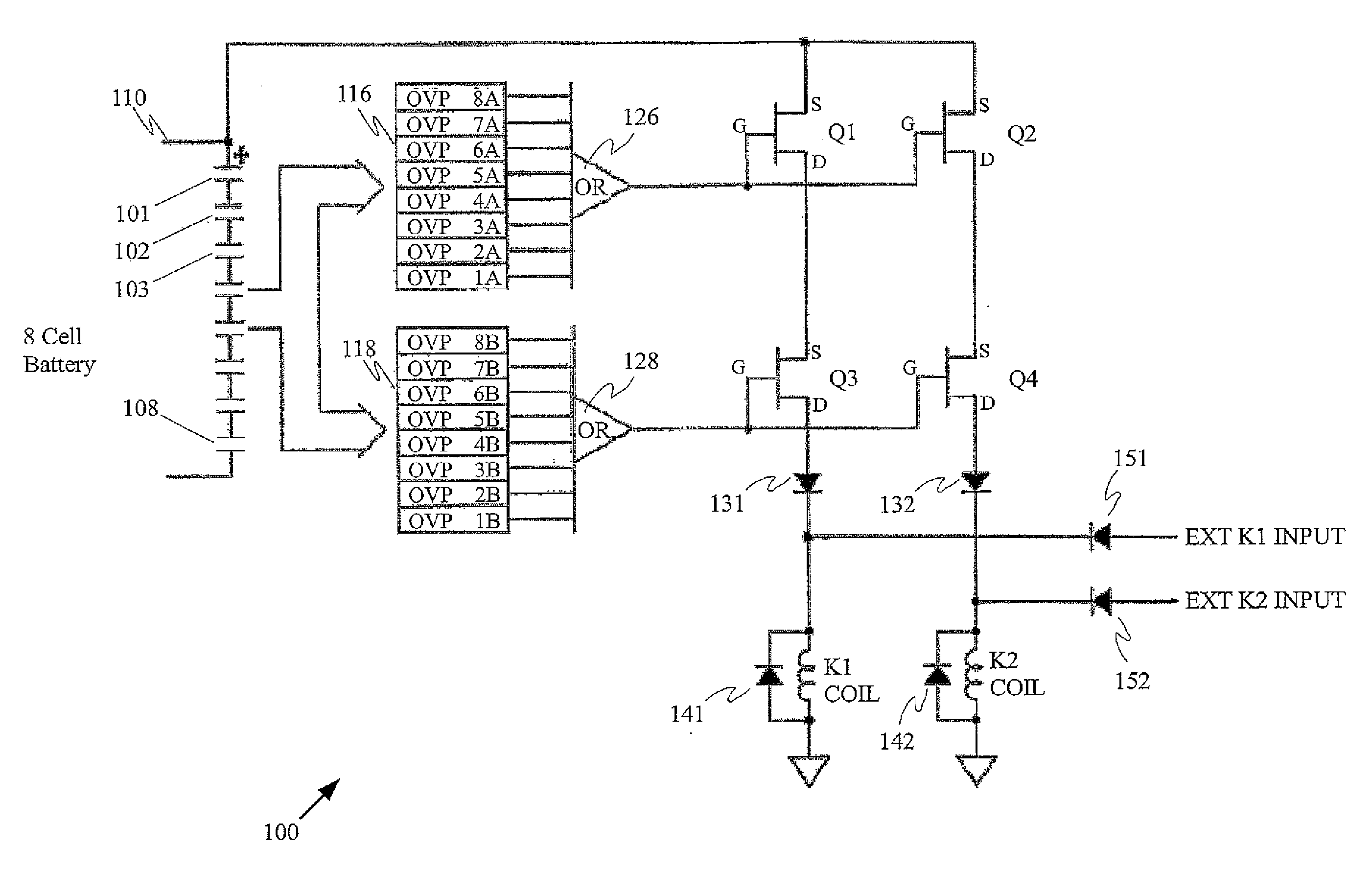
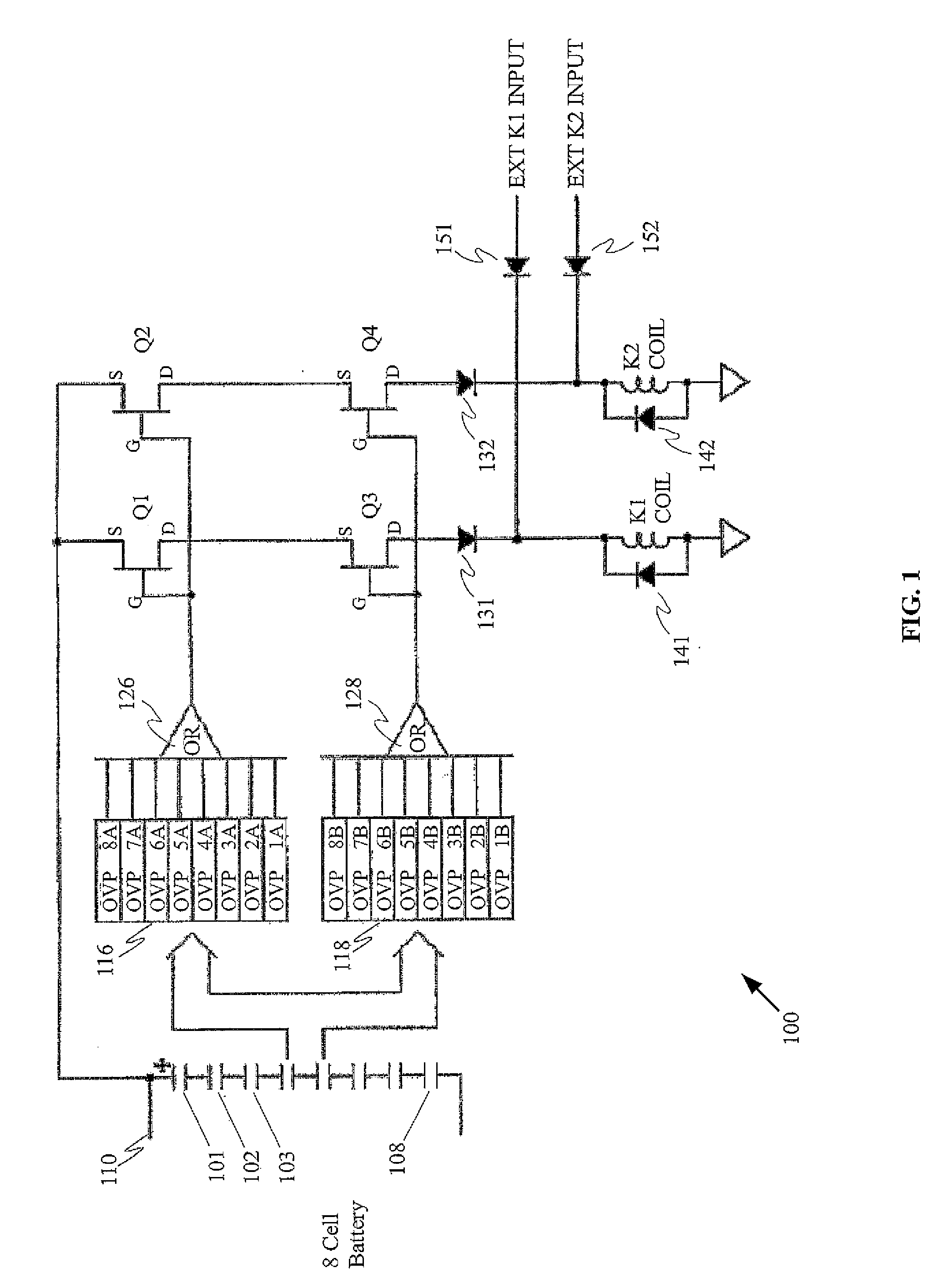
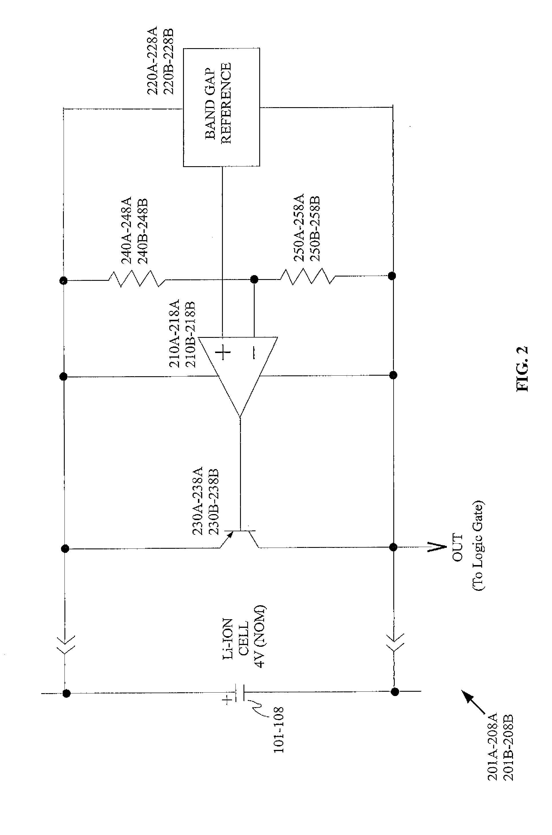
[0019]In accordance with at least one embodiment of the present invention, a battery may comprise multiple cells. While a multi-cell Li-ion battery may be utilized for the sake of explanation in the following disclosure, the various embodiments of the present invention are not intended to be limited to use with only this battery technology. The various embodiments of the present invention may be utilized with, for example, any power source or battery technology that may impose similar operational requirements in that the condition of the power source or battery must be regulated in order to maintain performance, or in more extreme cases, to avoid failure.

[0020]In the examples disclosed herein, circuits may be configured to prevent a lithium...


PUM


Abstract

A system comprises a battery including one or more cells, an energy source, a load, and a battery protection circuit coupled to the battery, the energy source and the load. The circuit determines if the charge of each cell is at/above a predetermined, band gap supplied threshold voltage, which results in disconnecting of the battery from the energy source. The circuit also may determine if the charge of any cell is at/below a second predetermined level, which may result in disconnecting of the battery from the load. The circuit may be radiation-hardened (e.g., via redundancy), through the use of two sets of field effect transistors, two logic gates, two groups of comparator circuits, and two relays. The circuit provides multiply redundant protection comprising: redundantly assessing the overvoltage determination; redundantly triggering battery isolation; and preventing inadvertent isolation and non-charging, occurring absent overvoltage, through redundant first and second relays.

Description

CROSS REFERENCES TO RELATED APPLICATIONS[0001]This application claims priority on U.S. Provisional Application Ser. No. 61 / 440,135 filed on Feb. 7, 2011, the disclosures of which are incorporated herein by reference.FIELD OF THE INVENTION[0002]The present invention relates to electronic circuits, and in particular, to a circuit configured to monitor the charge of one or more cells in a battery and to prevent the charge of each cell from exceeding, and in some instances also falling below, predetermined charge levels.BACKGROUND OF THE INVENTION[0003]Electronic apparatuses that cannot be continuously coupled to stationary power sources may instead employ localized sources of energy like batteries. The growing popularity of mobile apparatuses for use in communication, productivity, entertainment, etc. is an obvious example of how electronic devices may utilize batteries in order to support apparatus mobility. Batteries may be disposable or rechargeable, with technological development c...

Claims


Application Information

Patent Timeline
IPC IPC(8): H02H3/20
CPCH02J7/0026H02J7/0014H02J7/00302H02J7/00308H02J7/00306G01R31/2827H02H3/207H02J7/0031
Inventor ALTEMOSE, GEORGECONSI, MICHAEL
Owner COBHAM ADVANCED ELECTRONICS SOLUTIONS
Why Eureka
Try Eureka