

Fault current limitation in DC power transmission systems
- Summary
- Abstract
- Description
- Claims
- Application Information
AI Technical Summary
Benefits of technology
Problems solved by technology
Method used
Image

Examples
Embodiment Construction
[0046]In the following, a detailed description of preferred embodiments of the invention will be given.
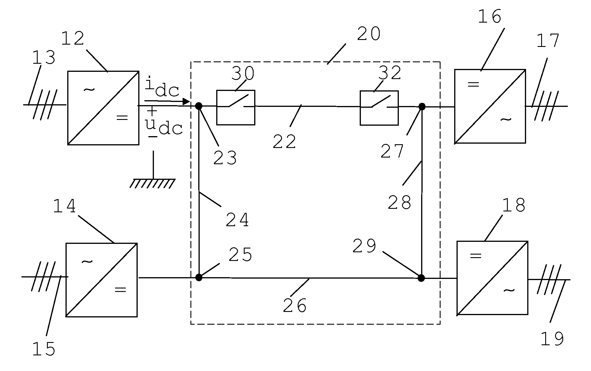
[0047]FIG. 1 shows a single line diagram of a simplified Direct Current (DC) power transmission system 20 being connected to four different Alternating Current (AC) power lines via voltage source converters 12, 14, 16 and 18. The power transmission system may with advantage be a High Voltage Direct Current (HVDC) system. There is here a first voltage source converter 12 having an AC side connected to a first AC power line 13 and a DC side connected to a first junction 23 between a first DC power line 22 and a second DC power line 24. There is also a second voltage source converter 14 having an AC side connected to a second AC power line 15 and a DC side connected to second junction 25 between the second DC power line 24 and a third DC power line 26. There is a also a third voltage source converter 16 having an AC side connected to a third AC power line 17 and a DC side connected to...
PUM
 Abstract
Description
Claims
Application Information