
Memory-Aided Synchronization In A Receiver

a synchronization and memory technology, applied in the direction of amplitude demodulation, digital transmission, electrical equipment, etc., can solve the problems of complex and time-consuming synchronization process, inability to finalize synchronization for multiple data frames, and inability to know additional information such as knowledge of an operative guard interval, so as to efficiently synchronize a demodulator to an incoming data stream and quickly perform synchronization

Active Publication Date: 2012-08-09
SILICON LAB INC
View PDF21 Cites 14 Cited by
  • Summary
  • Abstract
  • Description
  • Claims
  • Application Information

AI Technical Summary

Benefits of technology

[0004]One aspect of the present invention is directed to method that can be used to efficiently synchronize a demodulator to an incoming data stream. In general, the method may provide for replaying of at least some information, namely one or more preamble and data symbols of a frame, to more rapidly perform synchronization.
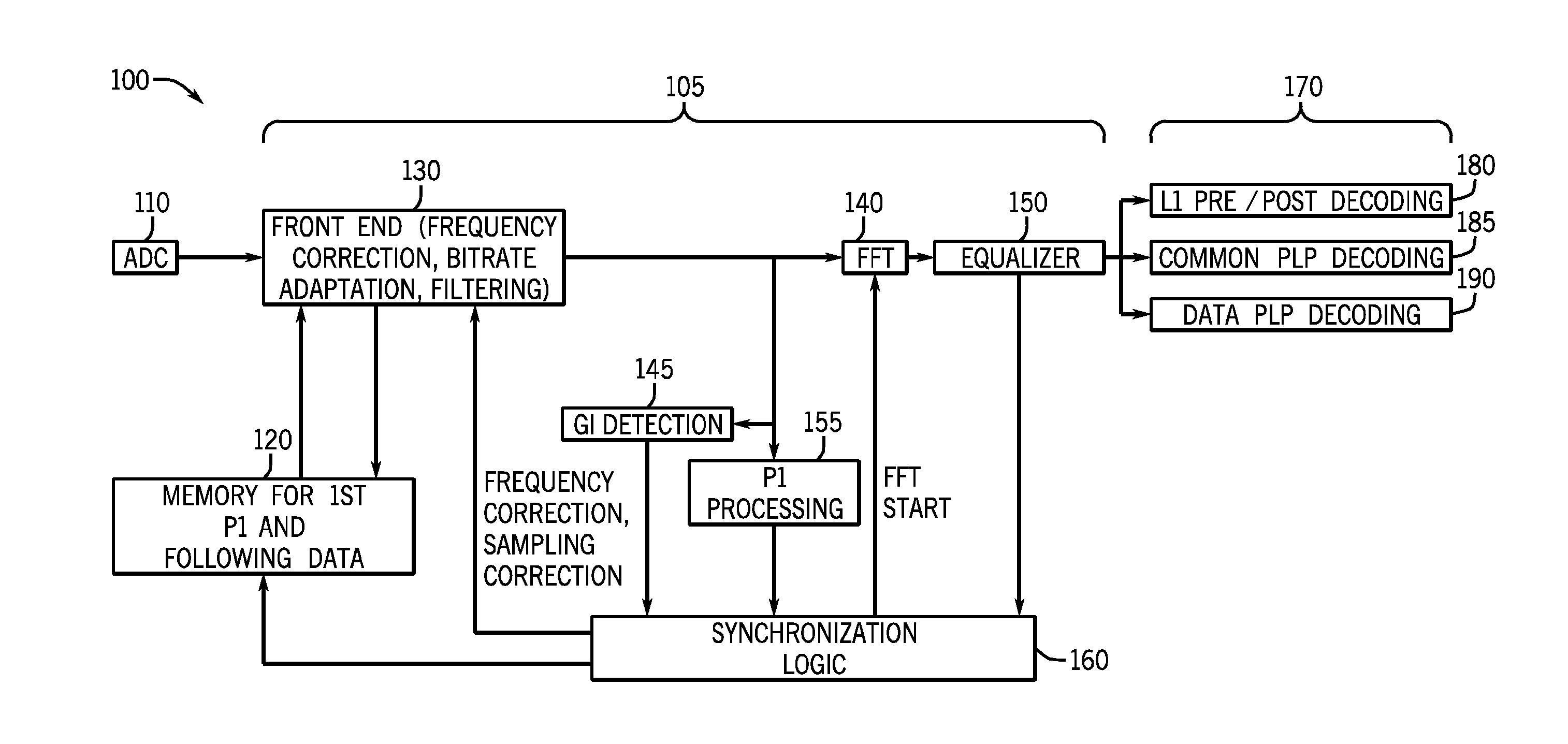
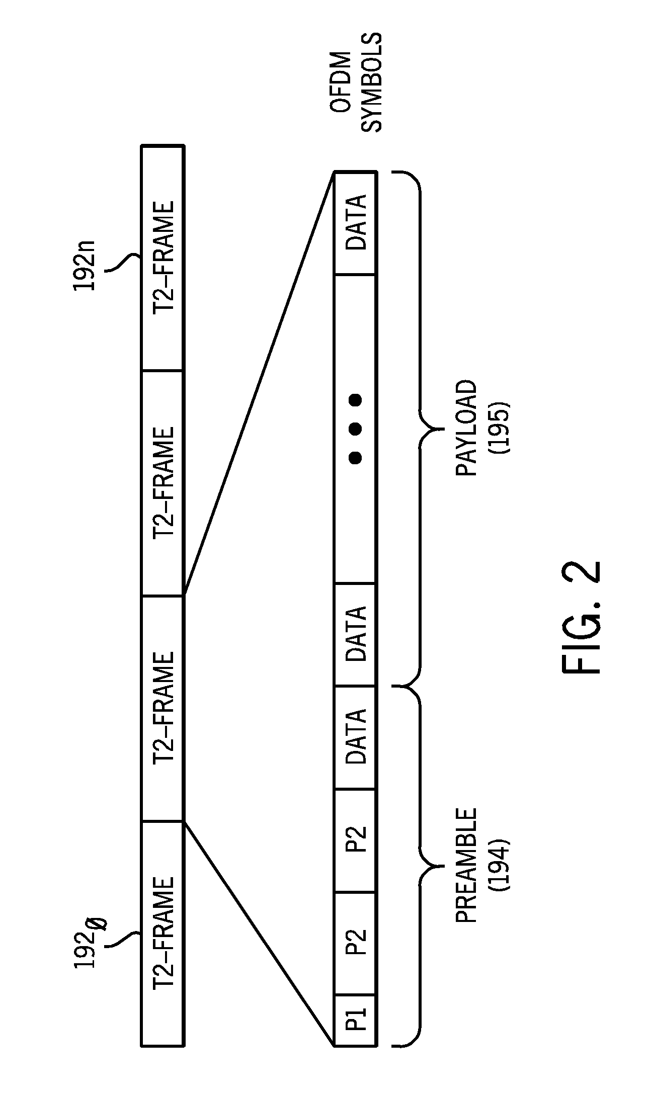
[0005]In one embodiment, the method may include storing information from a first frame of an incoming broadcast signal in a memory coupled to a demodulator, decoding a first preamble symbol of the first frame to determine a mode of a fast Fourier transform (FFT) engine of the demodulator, accessing at least some of the stored information from the memory and decoding at least one second preamble symbol of the first frame from the accessed information to determine pilot pattern information, and receiving data symbols of the first frame and synchronizing the demodulator based on the received data samples and the pilot pattern information. In this way, the demodulation can occur more rapidly, enabling the output of desired decoded data, e.g., in the form of a video broadcast to a display of a system.

Problems solved by technology

Currently, this synchronization process is complicated and time consuming.
However, even when some of the preamble information can be obtained and decoded from a first frame, additional information such as knowledge of an operative guard interval is not known.
Without this information, it becomes difficult or impossible to finalize synchronization for multiple data frames.
Also in DVB-T2 systems, the delay for decoding a first preamble symbol makes it also impossible to decode following symbols (additional preamble P2 or data symbols) on the fly.
This processing thus delays the end of the synchronization process, requiring additional time before valid channel information can be obtained.

Method used


Image

  • Memory-Aided Synchronization In A Receiver
  • Memory-Aided Synchronization In A Receiver
  • Memory-Aided Synchronization In A Receiver

Examples


Embodiment Construction

[0015]Embodiments may provide a memory that can be associated with a demodulator to aid in synchronization operations. That is, embodiments may provide a memory, which can be a standalone memory or a shared memory, for use in a synchronization process. To this end, the memory may store at least portions of an initial frame of an incoming data stream, e.g., at least the preamble portions, to enable their replay during synchronization to thus complete synchronization and lock the demodulator onto the incoming data stream in a more efficient manner. While embodiments described herein are used in connection with a terrestrial DVB-T2 implementation, it is to be understood that the scope of the present invention is not limited in this regard, and embodiments may be used in various communication systems, particularly where an encoding is according to an orthogonal frequency division multiplexing (OFDM) scheme.

[0016]Referring now to FIG. 1, shown is a block diagram of a portion of a receive...


PUM


Abstract

In one embodiment, a method may include storing information from a first frame of an incoming broadcast signal in a memory coupled to a demodulator, decoding a first preamble symbol of the first frame to determine a transmission mode, accessing at least some of the stored information from the memory and decoding at least one second preamble symbol of the first frame from the accessed information to determine pilot pattern information, and receiving data symbols of the first frame and synchronizing the demodulator based on the received data samples and the pilot pattern information.

Description

BACKGROUND[0001]Today, more and more television broadcasters are moving from analog broadcasting systems to digital broadcasting systems. Various standards are present for digital video broadcasting, where signals may be received by a selected one of various sources such as cable, satellite, and terrestrial. One available set of standards is referred to as the digital video broadcasting (DVB) standards.[0002]For terrestrial DVB communications, a channel is broadcast as a data stream having a series of data frames. To allow a receiver to lock onto a desired channel, a synchronization process is performed to enable a demodulator of the receiver to lock onto the signal stream.[0003]Currently, this synchronization process is complicated and time consuming. This is so, as preamble symbols of a data frame must first be decoded to obtain information needed for further steps in the synchronization process. However, even when some of the preamble information can be obtained and decoded from ...

Claims


Application Information

Patent Timeline
IPC IPC(8): H04L27/06
CPCH04L27/2663H04L27/2685H04L27/2675H04L27/2665
Inventor VAPILLON, ERICGUILLAUME, GAETANGAUTIER, EMMANUEL
Owner SILICON LAB INC
Learn More