
Sleep apnea test sensor assembly and sleep apnea test equipment using the same

a technology of sleep apnea and sensor assembly, which is applied in the field of sleep apnea test sensor assembly and sleep apnea test equipment using the same, can solve the problems of data instability, lowering the reliability of obtained sensing data, and increasing the number of wires, so as to achieve accurate diagnosis of sas

Inactive Publication Date: 2009-08-13
PANASONIC HEALTHCARE HLDG CO LTD
View PDF11 Cites 22 Cited by
  • Summary
  • Abstract
  • Description
  • Claims
  • Application Information

AI Technical Summary

Benefits of technology

"The present invention solves the problem of complex wires and unstable data in conventional sleep apnea test equipment by providing a sensor assembly with multiple sensors that operate independently without wires. The sensors each have a storage unit for measuring data, and a control unit for setting time based on a synchronous signal. This eliminates the need for long wires and reduces the burden on the patient to attach sensors. The sensor assembly includes multiple sensors such as temperature sensors, acoustic sensors, light sensors, and acceleration sensors, which can measure sensing data with the synchronization in time being secured. The sensor assembly is easy to use, comfortable for the examinee, and secure against sensor falling off. The sleep apnea test equipment comprises the sensor assembly and a main apparatus with a storage section for storing the multiple sensors and a control unit for outputting a synchronous signal to control time of the multiple sensors."

Problems solved by technology

However, in a conventional test equipment, many sensors are connected to the data recorder by long wires, so that the wires become more complicated with an increase in the number of sensors which causes an increase in the number of wires.
Thus, if the examinee is not well trained with the test equipment, there is a risk of not noticing wire misconnection or wire falling off, thereby lowering the reliability of the obtained sensing data.
Further, when the posture of the examinee changes during sleep, there is a risk that a sensor may come off the body of the examinee, or a wire may fall off the data recorder, thereby causing the data to be unstable.
If the posture of the examinee is restricted to prevent the wire falling off, there is a risk of disturbing the sleep of the examinee.
However, in the screening test done by the examinee at home, it is not possible to properly handle e.g. the wire falling off because the examinee itself is not well trained with the test equipment.
However, there is a risk that an obstacle to block a wireless signal may be present in the bedroom of the home of the examinee, and that depending on the posture of the sleeping examinee, the wireless signal transmitted from the sensor may not be stably received by the data recorder.
Furthermore, the sensor attached to the body becomes more likely to come off the body if the transmission power is increased to stabilize the data transmission, which causes an increase in the size of a battery installed in the sensor and an increase in the weight of the sensor.
However, according to this method, it is difficult to synchronize the time relationship between the respective sensors to match each other.
If the time relationship of the respective sensors is not synchronized, it is not possible to compare the correlation between the measured data of the respective sensors, so that accurate data analysis and diagnosis of SAS cannot be expected.
Thus, in the screening test to comprehensively analyze the measured data for the diagnosis of SAS, an error of about 10 seconds between the respective sensors exerts a fatal influence.

Method used


Image

  • Sleep apnea test sensor assembly and sleep apnea test equipment using the same
  • Sleep apnea test sensor assembly and sleep apnea test equipment using the same
  • Sleep apnea test sensor assembly and sleep apnea test equipment using the same

Examples


Embodiment Construction

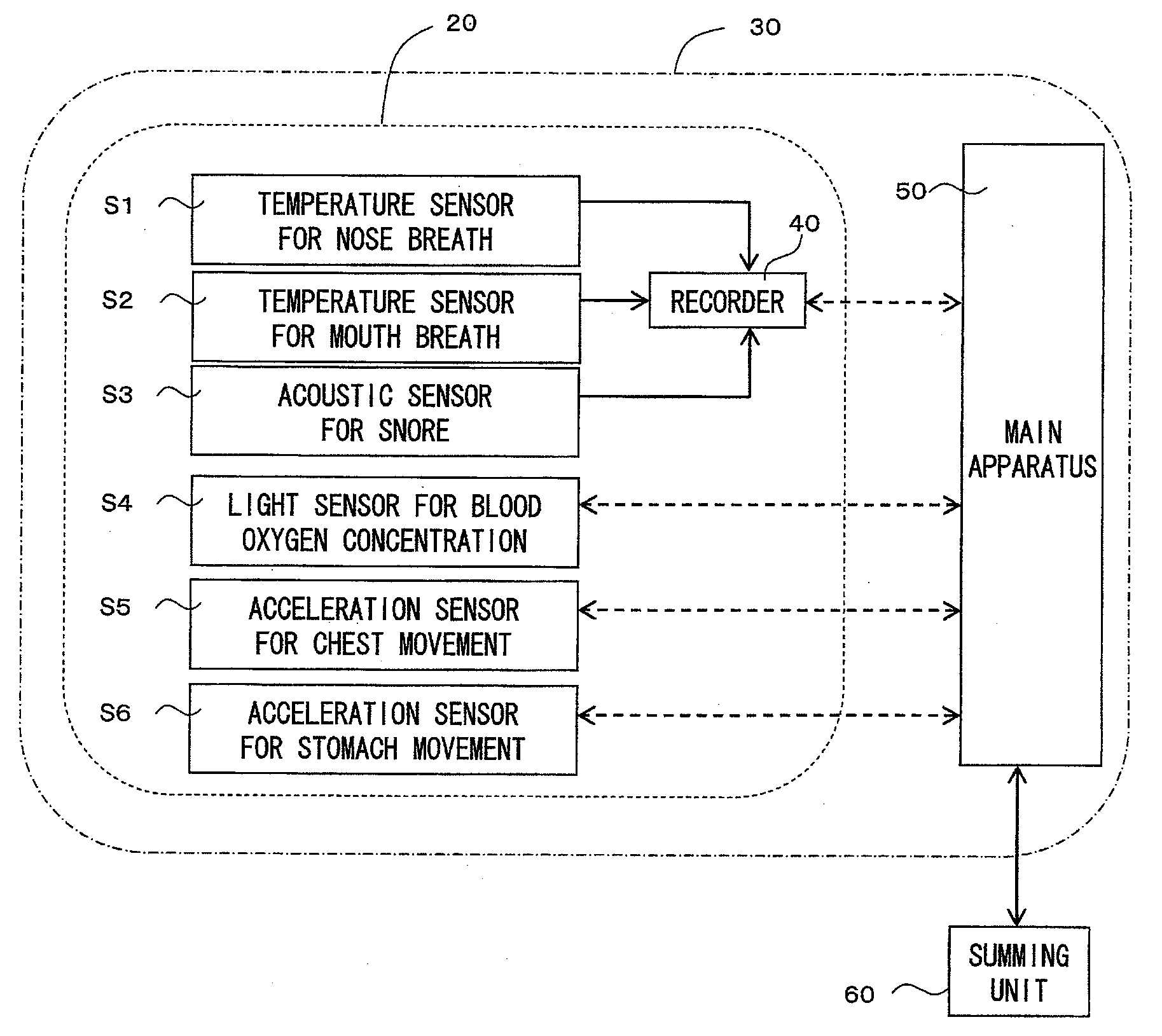
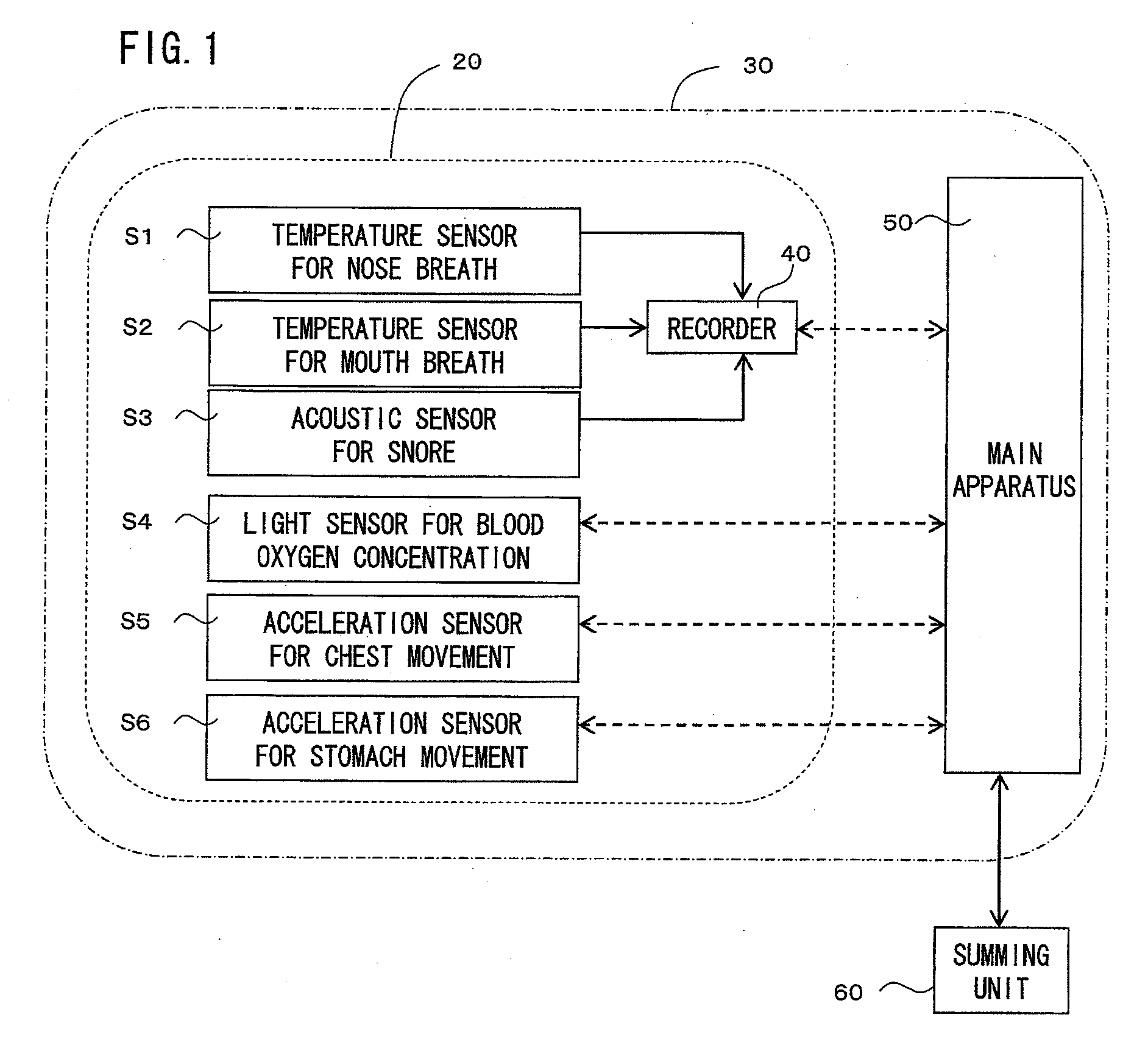
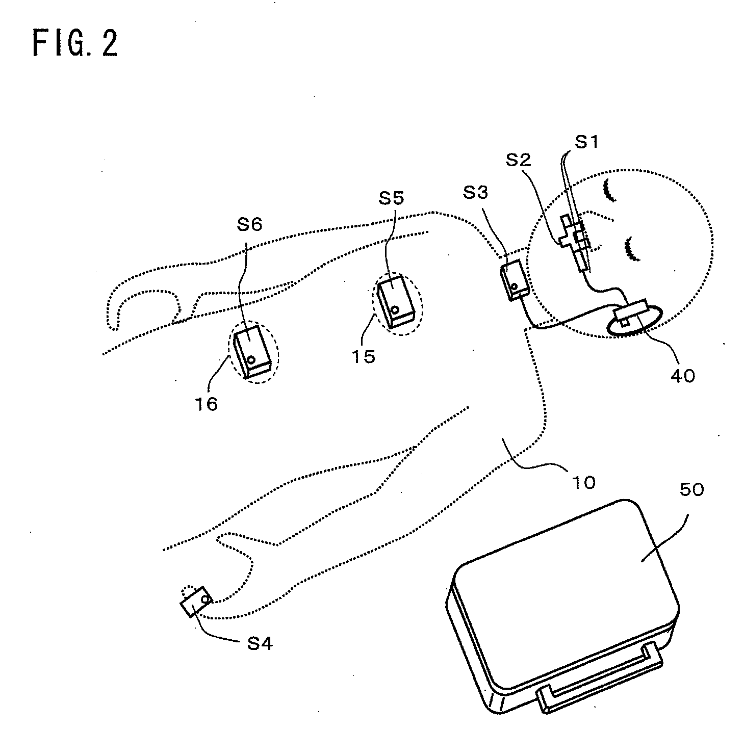
[0022]A schematic configuration of a sleep apnea test sensor assembly (hereafter referred to as sensor assembly) and a sleep apnea test equipment comprising this sensor assembly according to an embodiment of the present invention will be described with reference to FIG. 1 and FIG. 2. A sensor assembly 20 of the present embodiment comprises multiple sensors comprised of an appropriate combination of at least two of a temperature sensor S1 for measuring mouth (sic, correctly: nose) breath, a temperature sensor S2 for measuring nose (sic, correctly: mouth) breath, an acoustic sensor S3 for measuring snore, a light sensor S4 for measuring blood oxygen concentration, an acceleration sensor S5 for measuring chest movement, and an acceleration sensor S6 for measuring stomach movement.

[0023]The sensor assembly 20 enables more accurate diagnosis of SAS with an increase in the number of kinds of sensors to be combined, but can be put to practical use if at least two kinds of them are combined...


PUM


Abstract

This relates to a sleep apnea test sensor assembly (20) comprising multiple sensors to be used for diagnosis of sleep apnea syndrome, and a test equipment (30) comprising the same. The respective sensors each associate sensing data measured by a respective sensing section with time data of a clock unit, and store them in a storage unit so as to allow the sensing section to perform sensing at a predetermined period in response to a clocking operation of the clock unit, and set time of the clock unit in response to a synchronous signal input from outside. The respective sensors operate physically independently of each other, but can measure sensing data with the synchronization in time therebetween being secured, enabling accurate diagnosis of SAS.

Description

TECHNICAL FIELD[0001]The present invention relates to a sleep apnea test sensor assembly comprising multiple sensors to be used for diagnosis of sleep apnea syndrome, and a sleep apnea test equipment using the same.BACKGROUND ART[0002]Sleep apnea syndrome (SAS) is considered to be one of the sleep disorders. Generally, a sleep polysomnography test is used for diagnosis of this SAS. This test uses a sleep apnea test equipment having many bioinstrumentation sensors such as e.g. a snore sensor, an oronasal airflow sensor, an arterial blood oxygen saturation sensor, a chest movement sensor, a stomach movement sensor, and so on. In this sleep polysomnography test, sensing data from each sensor is stored in a data recorder connected to each sensor. Then, a professional such as a doctor diagnoses SAS by analyzing the features of the change rates of these sensing data and the correlations between the data. The diagnosis accuracy of SAS is expected to increase by using multiple sensors as in...

Claims


Application Information

Patent Timeline
Patent Type & Authority Applications(United States)
IPC IPC(8): A61B5/08
CPCA61B5/0002A61B5/0205A61B5/0878A61B5/097A61B5/113A61B5/1455A61B2560/0431A61B5/681A61B5/6814A61B5/6815A61B5/6826A61B5/6838A61B7/003A61B5/4818
Inventor FUKUSHIMA, SHOGOYAMAMOTO, MATSUKI
Owner PANASONIC HEALTHCARE HLDG CO LTD
Learn More