Optical packet switching system and optical packet transmitter device

a technology of optical packet switching and optical packet transmitter, which is applied in data switching networks, wavelength-division multiplex systems, multiplex communication, etc., can solve the problem of bandwidth waste and other problems, and achieve the effect of high priority and high speed

Inactive Publication Date: 2012-08-09
FUJITSU LTD
View PDF42 Cites 17 Cited by
  • Summary
  • Abstract
  • Description
  • Claims
  • Application Information

AI Technical Summary

Benefits of technology

[0008]The present invention addresses the background as described above, and a purpose thereof is to provide a technology

Problems solved by technology

When the transmission is based on IP packets, no significant information i

Method used


Image

  • Optical packet switching system and optical packet transmitter device
  • Optical packet switching system and optical packet transmitter device
  • Optical packet switching system and optical packet transmitter device

Examples


Embodiment Construction

[0034]The invention will now be described by reference to the preferred embodiments. This does not intend to limit the scope of the present invention, but to exemplify the invention.

[0035]A description will now be given of the optical packet switching system according to an embodiment of the present invention. Prior to an explanation of the optical packet switching system according to the embodiment of the present invention, an explanation is given as a comparative example regarding an optical packet switching system conventionally developed by the present inventors.

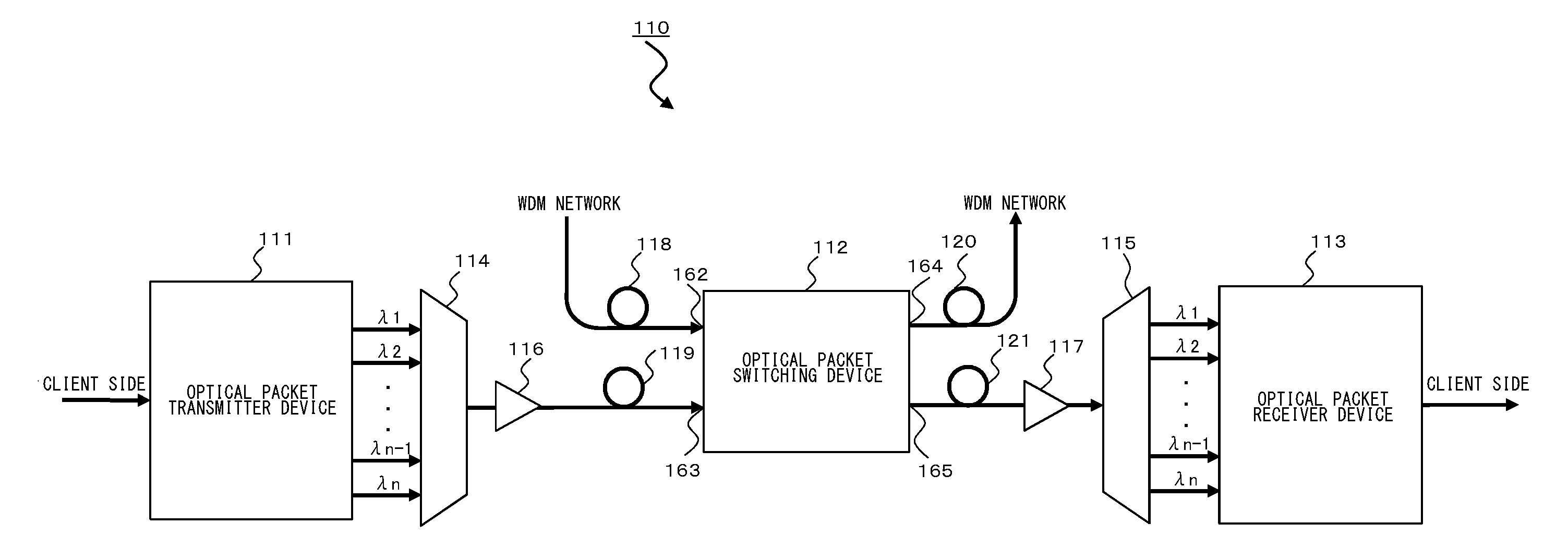
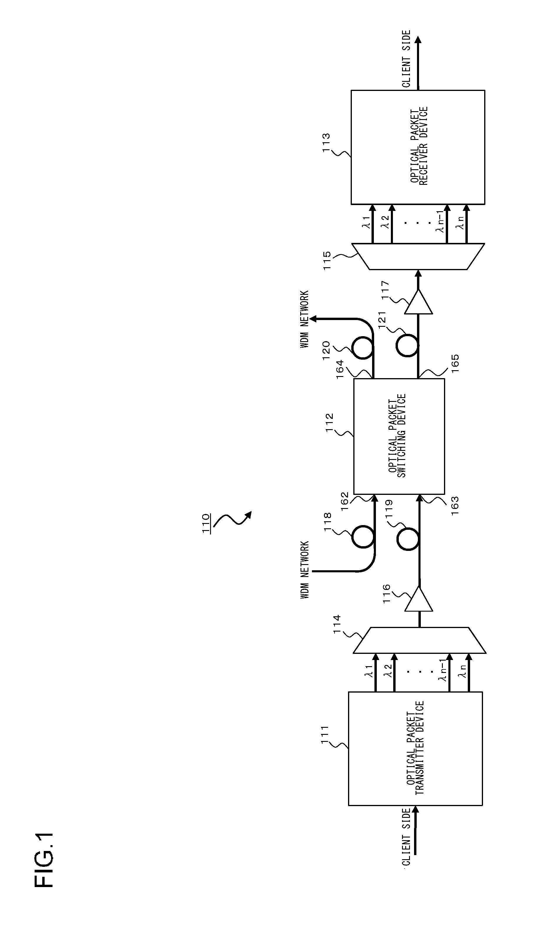
[0036]FIG. 1 shows an optical packet switching system 110 according to the comparative example. As shown in FIG. 1, the optical packet switching system 110 comprises an optical packet transmitter device 111, an optical packet switching device 112, an optical packet receiver device 113, a first AWG 114, a second AWG 115, a first optical amplifier 116, a second optical amplifier 117, and first through fourth optical transm...


PUM


Abstract

An optical packet transmitter device includes: a detection unit for detecting packet-length information and priority information from a received Ether signal; a setting unit for setting, according to the degree of priority, a division factor by which the Ether signal is divided and a wavelength used for an optical packet signal to be transmitted; a header generation unit for generating a header containing destination information, the packet-length information, the priority information, and information of wavelength in use of the Ether signal; a transmission processing unit for dividing the Ether signal according to the set division factor and generating a plurality of packet signals; a header insertion unit for inserting the generated header in at least one packet signal; and an electrical/optical converter unit for converting the plurality of packet signals into optical packet signals of a plurality of wavelengths according to the set wavelength in use.

Description

BACKGROUND OF THE INVENTION[0001]1. Field of the Invention[0002]The present invention relates to an optical packet switching method in which packet-by-packet optical packet switching is enabled by driving an optical switch according to destination information assigned to an optical packet signal.[0003]2. Description of the Related Art[0004]The technology of switching the path depending on the wavelength in an optical transmission system based on wavelength division multiplexing (WDM) and by employing a wavelength selective switch (WSS) is in practical use. One of the next-generation technologies studied is an optical packet switching system in which the path is switched in smaller units, namely, IP packets (10 Gigabit Ethernet (registered trademark) signals, etc.). Each packet is converted in format into an optical packet and routed by using an ultrahigh-speed optical switch (see e.g., patent document No. 1).[0005]When the transmission is based on IP packets, no significant informat...

Claims


Application Information

Patent Timeline
IPC IPC(8): H04J14/02H04L12/56H04B10/27H04B10/07H04B10/291H04L12/701H04L12/937
CPCH04L45/62H04Q11/0005H04Q2011/0039H04Q2011/0016H04Q11/0066
Inventor UEKAMA, KIMIOMORI, SHOTA
Owner FUJITSU LTD
Why Eureka
Try Eureka