Brain Machine Interface Device

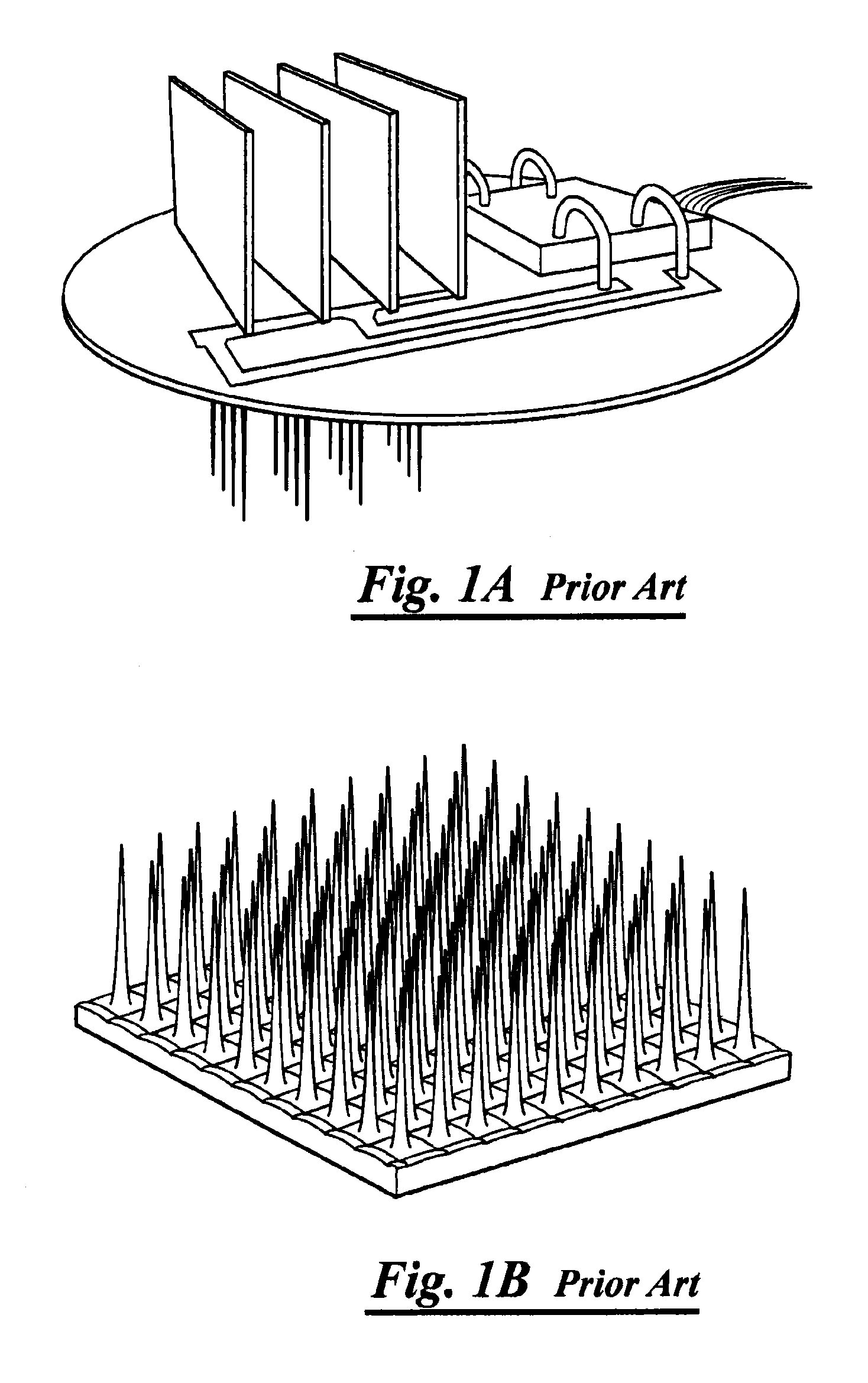
a brain machine and interface technology, applied in the field of brain machine interface devices, can solve the problems of affecting their functionality and longevity, devices cannot be used to monitor deep structures or be distributed across or within the brain, and monolithic design not only significantly limits their usefulness, but also has several detrimental characteristics

Inactive Publication Date: 2012-08-09
RENNAKER II ROBERT L
View PDF3 Cites 24 Cited by
  • Summary
  • Abstract
  • Description
  • Claims
  • Application Information

AI Technical Summary

Problems solved by technology

Not only does the monolithic design construct limit the depth of the interface, but there are several other structural characteristics that significantly impact their functionality and longevity.
Due to the monolithic structure, these devices cannot be used to monitor deep structures or be distributed across or within the brain.
Their monolithic design not only significantly limits their usefulness but have several detrimental characteristics.
The wires and connectors are a major source of failure for these devices.
Depending on the particular neural interface, the design constraints significantly change.
The use of external capacitors is not feasible.
The use of RF to transmit at this rate would require unsafe power levels for an implanted device.
The major issue for most of the spike detections is setting the threshold correctly.
These wires can provide a route of infection and are a significant source of failure.
Very little work has focused on powering device inside the skull.
The drawbacks to microwire designs are that they are highly prone to motion artifact making it nearly impossible to record from behaving animals, the wires must pass through the skull and skin and they have several of the design flaws found in the monolithic structures as discussed below.
First it is hand made, and therefore cannot be manufactured in large quantities.
Second, the wires must pass through the skull and skin.
This design is susceptible to damaged connectors and noise from external sources.
These devices perform excellent for their intended applications, but they are limited to interfacing with superficial structures.
An analysis of the monolithic designs reveals many inherent design features that limit their functionality.
These devices are limited to recording from cells near the surface.
These devices typically cannot record from structures deeper than 5 mm.
This motion could result in injury to the surrounding tissue including neurons and blood vessels.
Overtime, it would be expected that considerable damage would be induced around the implant site resulting in a loss of neural information.
Violent head movements could result in the probe striking the inside of the skull, damaging cortical tissue and the device.
Robustness—Because the devices physically cannot overlap, failure of the probe would result in loss of all data from that neural population.
Yield—The rigid structure does not allow the recording sites to be independently positioned.
It is likely that some portion of the recording sites will not provide viable neural recordings.
Complexity—These designs are highly complex and require a large number of interconnects.
The large number of interconnects and complexity provide a large number of potential failure points.
Failure at critical points could result in a loss of all data from that neural interface.

Method used


Image

  • Brain Machine Interface Device
  • Brain Machine Interface Device
  • Brain Machine Interface Device

Examples


Embodiment Construction

[0043]Presently preferred embodiments of the invention are shown in the above-identified figures and described in detail below. In describing the preferred embodiments, like or identical reference numerals are used to identify common or similar elements. The figures are not necessarily to scale and certain features and certain views of the figures may be shown exaggerated in scale or in schematic in the interest of clarity and conciseness.

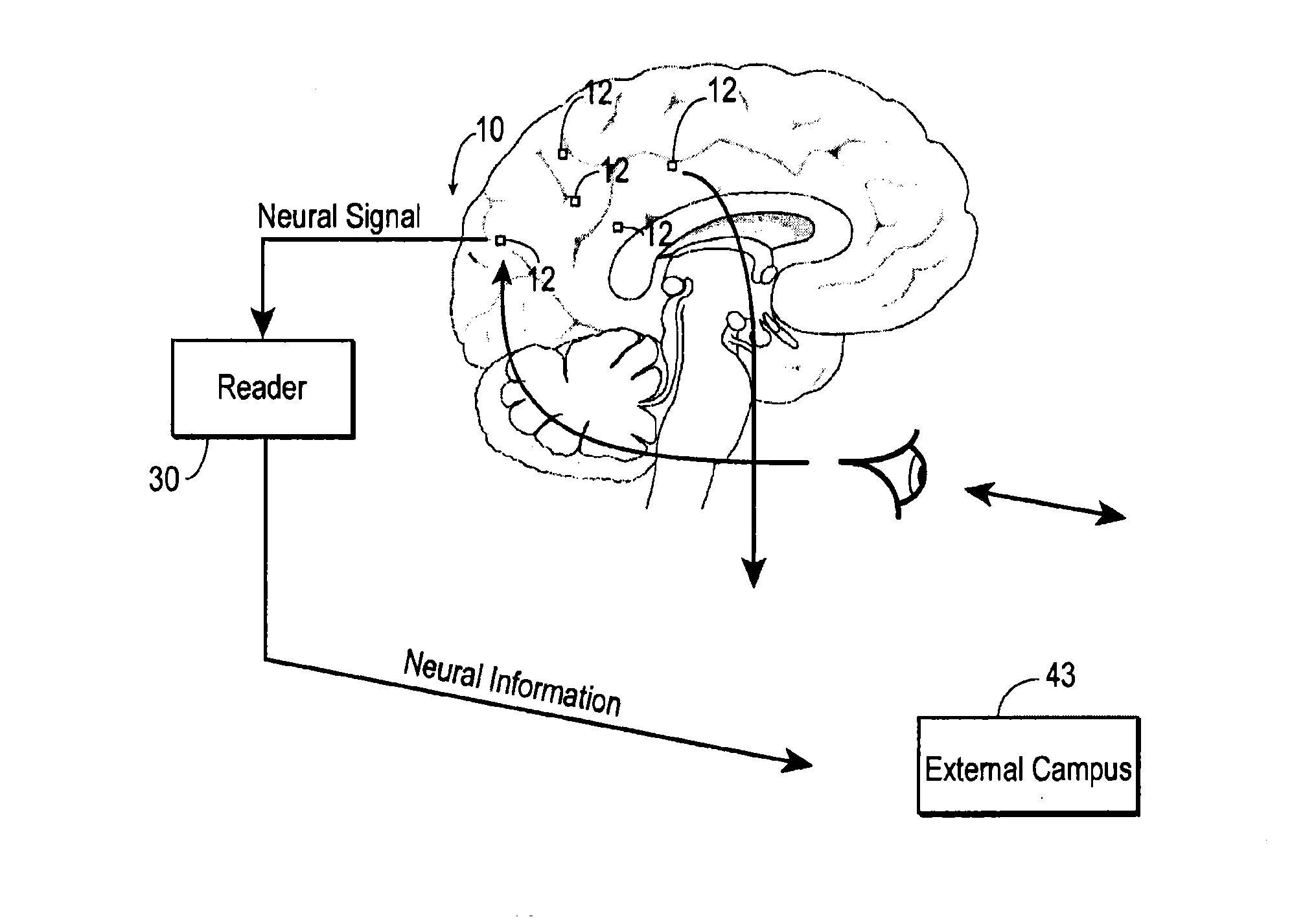
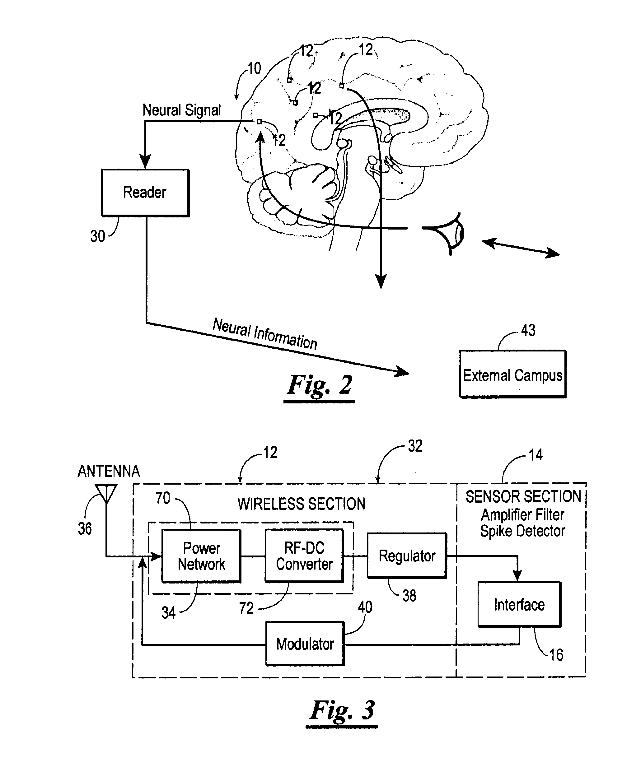
[0044]Referring now to the drawings and in particular to FIG. 2, shown therein and designated by a reference numeral 10 is a distributed real-time wireless neural interface constructed in accordance with the present invention. The neural interface 10 is capable of overcoming the limitations inherent in current state-of-the-art monolithic neural interfaces. The neural interface 10 includes a distributed array of independent wireless single-channel extracellular recording probes 12. Only five of the probes 12 are shown for purposes of brevity. Each i...


PUM


Abstract

A distributed real-time wireless neural interface including a reader and an array of distinct recording devices having a wireless section and a sensor section. The reader outputs and receives radio-frequency signals. The wireless section of the array includes an rf power converter, an antenna, a regulator, and a modulator. The antenna receives the radio-frequency signals output by the reader and provides the radio-frequency signals to the rf power converter which converts such radio-frequency signals to power signals. The regulator receives the power signals and regulates such power signals to provide stable power signals. The sensor section receives the stable power signals and is adapted to detect neural activity and provide output signals containing information indicative of such neural activity to the modulator. The modulator receives the power signals and the output signals from the sensor section communicates the information in the output signals to the reader via the antenna.

Description

CROSS-REFERENCE TO RELATED APPLICATIONS[0001]The present patent application is a continuation of U.S. Ser. No. 11 / 346,507, filed on Feb. 1, 2006, which claims priority to the provisional patent application identified by U.S. Ser. No. 60 / 649,728, filed on Feb. 3, 2005, the entire contents of which are hereby incorporated herein by reference.STATEMENT REGARDING FEDERALLY SPONSORED RESEARCH AND DEVELOPMENT[0002]Not Applicable.BACKGROUND OF THE INVENTION[0003]The human nervous system encodes information using electrical signals known as action potentials (spikes) which are generated by neurons and sensory receptors. The brain is a highly organized complex structure composed of billions of neurons which integrates multimodal sensory information to control behavior. A sensor capable of providing a stable, robust connection in humans could be used to study, treat, monitor treatments or diagnose neurological conditions. A wide range of neurological conditions could benefit from such a devic...

Claims


Application Information

Patent Timeline
Patent Type & Authority Applications(United States)
IPC IPC(8): A61B5/0476
CPCA61B5/04001A61B5/0002A61B5/24
Inventor RENNAKER, II, ROBERT L.
Owner RENNAKER II ROBERT L
Why Eureka
Try Eureka