Graft Systems Having Semi-Permeable Filling Structures and Methods for Their Use

a semi-permeable, filling structure technology, applied in the field of expandable prosthesis, can solve problems such as shrinkage of filling structure, and achieve the effects of increasing the total filling capacity of filling structure, adequate sealing, and increasing the available spa

Inactive Publication Date: 2012-08-09
ENDOLOGIX LLC
View PDF32 Cites 35 Cited by
  • Summary
  • Abstract
  • Description
  • Claims
  • Application Information

AI Technical Summary

Benefits of technology

[0017]In another aspect, the outer or inner wall of the filling structure, or at least a portion thereof, may comprise the semi-permeable membrane. In some embodiments, the inner wall may comprise an impermeable material, while the outer wall may comprise a semi-permeable material. This prevents transport of fluid from the blood flowing through the generally tubular lumen across the membrane, while allowing for the flow of serum from the inside surface of the aneurysm and / or thrombus, promoting resolution or resorption of the thrombus and shrinkage of the aneurysm. The filling structures of the prosthesis will usually be formed from a non-compliant material, such as parylene, polyester (e.g., Dacron), PET, PTFE, and / or a compliant material, such as silicone, polyurethane, latex, or combinations thereof. Usually, it is preferable to form at least the outer wall partially or entirely from a non-compliant material to enhance conformance of the outer wall to the inner surface of the aneurysm. This is particularly true when the aneurysm has been individually designed and / or sized for the patient being treated. The walls of the filling structure may be a polymer material, such as polyurethanes, including a non-porous ePTFE coated or rolled with polyurethane. The total thickness of the inner and / or outer walls may range from 20 μm to 120 μm, and are preferably about 40 μm. Water vapor permeability of the wall material may be within a range from about 0.01 to about 0.03 mL / day / cm2, and is preferably about 0.015 mL / day / cm2.
[0018]The fluid filling medium comprises one or more filling fluids, at least one of which may include a hardenable polymer. Preferably, the hardenable polymer comprises a hydrogel polymer, such as polyethylene glycol PEG. The filling medium may be selected so as to have an osmolarity (or dissolvable solutes for causing an osmolarity) to induce a desired water potential differential sufficient to cause permeation of water molecules across the membrane as needed to enlarge or shrink the filling structure to adjust for changes in the morphology of the aneurysm. The pressure within the filling structure may be controlled through selection of a filling medium which imparts a desired osmotic pressure to the fluid inside the fillable space (such as through dissolvable solutes in the fluid filling medium). By providing the necessary water potential in the filling structure, the permeation of water molecules through the membrane can be controlled to expand or contract the filling structure as needed. For example, providing a filling medium having a water potential lower than the surrounding environment outside the filling structure, such as a hydrophilic PEG having dissolvable solutes, causes fluid flow across the semi-permeable material into the filling structure, thereby enlarging the filling structure and increasing the pressure inside the filling structure until equilibrium is reached. Providing a filling medium having an osmolarity lower than the surrounding environment outside the filling structure causes fluid flow out from the filling structure, thereby shrinking the filling structure. By selectively expanding or contracting the filling structure, the system can accommodate changes in the size or shape of the aneurysm, maintain apposition of the filling structure with the inside surface of the aneurysm, and maintain a pressure inside the filling structure to adequately seal the aneurysm.
[0022]In another aspect, the filling structure is oversized relative to the aneurysm, such that the total filling capacity of the filling structures is greater than the aneurismal space being treated. The oversized structure allows for expansion of the filling structure to accommodate an increase in available space inside the aneurysm as thrombus resorbs. In many embodiments, the outer wall of the filling structure may comprise folds which unfurl as the filling structure expands so as to maintain apposition between the outer wall and the inside surface of the aneurysm and to maintain an adequate pressure inside the filling structure to ensure an adequate seal between the filling structure and the inside surface of the aneurysm.
[0023]In addition to the filling structures just described, the aneurysm treatment systems may further include at least a first scaffold separate from the filling structure, where the scaffold can be expanded within or around the generally tubular lumen which provides the blood flow after the filling structure has been deployed in the aneurysm. The first scaffold will be adapted to expand within at least a first portion of the tubular lumen of the filling structure and may provide one or more specific advantages. For example, the scaffold may support and smooth the inside wall of the tubular lumen which in some cases might otherwise become uneven during hardening of the polymer fill. Scaffolds may also provide for anchoring of the filling structure, particularly at the aortic end of the graft when placed in an AAA. The scaffold may be partly or wholly covered with a membrane in order to form a graft. In such cases, the graft structure may help provide a transition from the blood vessel into the generally tubular lumen of the filling structure from the aortic end. Alternatively, the graft structure could provide one or a pair of transitions out of the iliac end of the filling structure. In a particular example, a graft structure can be used on either side of the filling structure in order to treat additional or continuing aneurismal regions in the adjacent blood vessel. In some embodiments, two or more filling structures may be used across the aneurysm. In such embodiments, a scaffold or multiple scaffolds may be placed within each filling structure.
[0024]Preferred delivery protocols for the filling structures will utilize delivery catheters having a balloon or other expandable support for carrying the filling structure. When using balloons, the balloons will preferably be substantially or entirely non-compliant, although compliant and combination compliant / non-compliant balloons may also find use. The balloon or other mechanical expansion components of the delivery catheter will initially be disposed within the inner tubular lumen of the filling structure, with the filling structure generally being collapsed into a low width or low profile configuration over the expansion element. The delivery catheter may then be introduced intraluminally, typically into the femoral artery and upwardly to the region within the aorta to be treated. The delivery catheter will also include one or more lumens, tubes, or other components or structures for delivering the filling medium in a fluid form to an internal filling cavity of the filling structure. Thus, the delivery catheter can be used to both initially place and locate the filling structure of the prosthesis at the aneurismal site. Once at the aneurismal site, the internal tubular lumen of the structure can be expanded using the balloon or other expandable element on the delivery catheter. The filling medium may be selected so that the medium has a quantity of dissolvable solutes sufficient to impart a concentration of solutes into the finable space so as to create the desired osmotic pressure in the fillable space. The membrane may be selected to allow transport of water molecules across the membrane to maintain a pressure inside the filling structure to adequately seal the aneurysm. The filling structure itself will be filled and expanded by delivering the filling medium via the catheter into the internal volume of the filling structure. Both expansion and filling operations may be performed simultaneously, or can be performed in either order, i.e. the filling structure may be filled first with the delivery catheter balloon being expanded second, or vice versa. The filling structure(s) and / or delivery balloons may have radiopaque markers to facilitate placement and / or pressure sensors for monitoring filling and inflation pressures during deployment. Once deployed, transport of water molecules through the semi-permeable material maintains the seal between the filling structure and the aneurysm, as well as the apposition of the outer wall to the inside surface of the aneurysm, expanding the outer wall outward when fluid flows into the filling structure and shrinking the structure when fluid flows out of the structure. This also helps to ensure that the filling structure is anchored in the aneurismal space, and does not migrate over time. In one aspect, the filling medium is selected so as to provide a salinity within the bag that is slightly above the high range of blood salinities that are likely to be experienced in the patient population so as to create an osmotic pressure (osmotic gradient) that is slightly positive. In another aspect, the osmotic pressure gradient provided is such that the bag does not shrink over time.

Problems solved by technology

Providing a filling medium having an osmolarity lower than the surrounding environment outside the filling structure causes fluid flow out from the filling structure, thereby shrinking the filling structure.

Method used


Image

  • Graft Systems Having Semi-Permeable Filling Structures and Methods for Their Use
  • Graft Systems Having Semi-Permeable Filling Structures and Methods for Their Use
  • Graft Systems Having Semi-Permeable Filling Structures and Methods for Their Use

Examples


Embodiment Construction

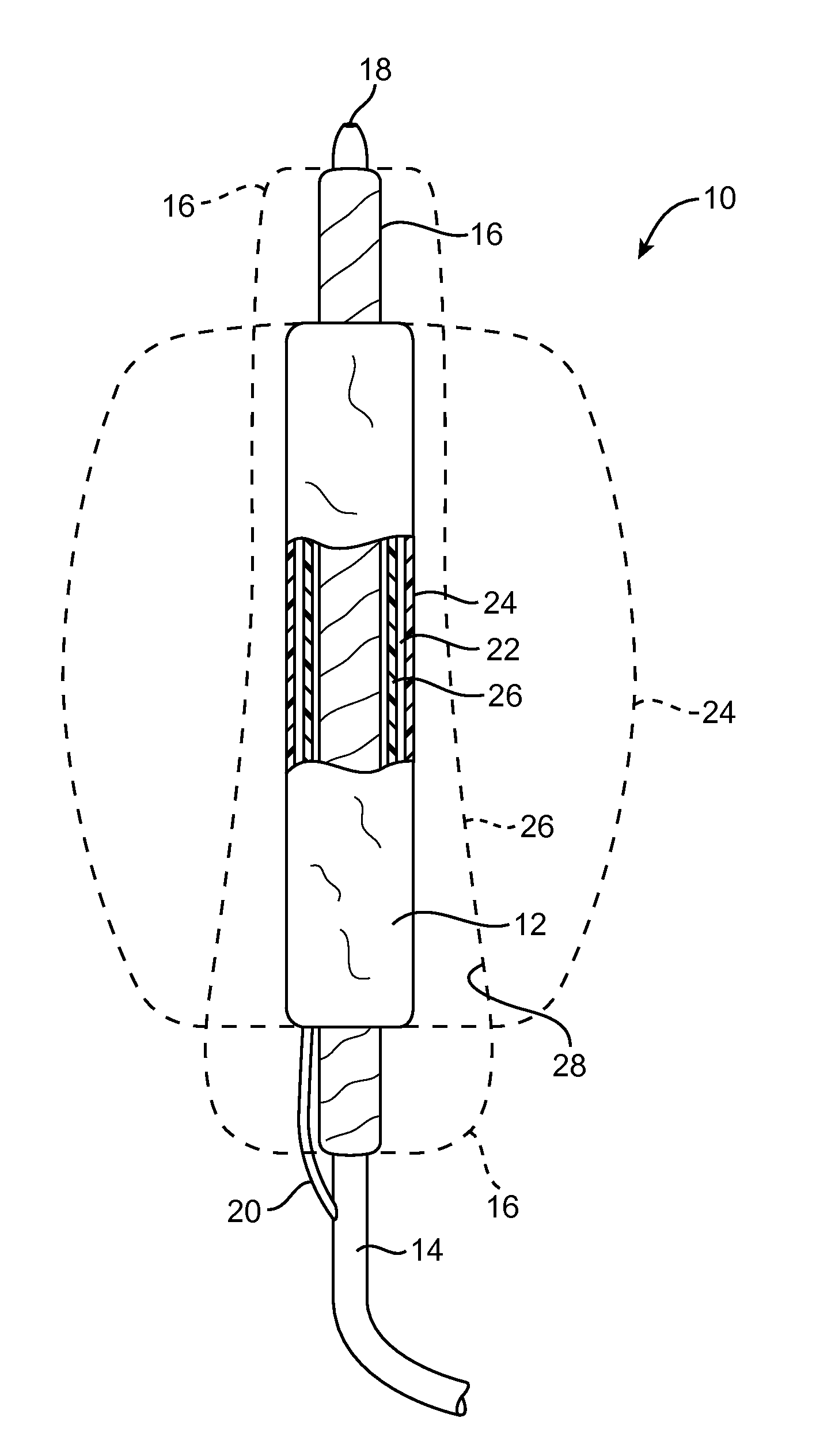
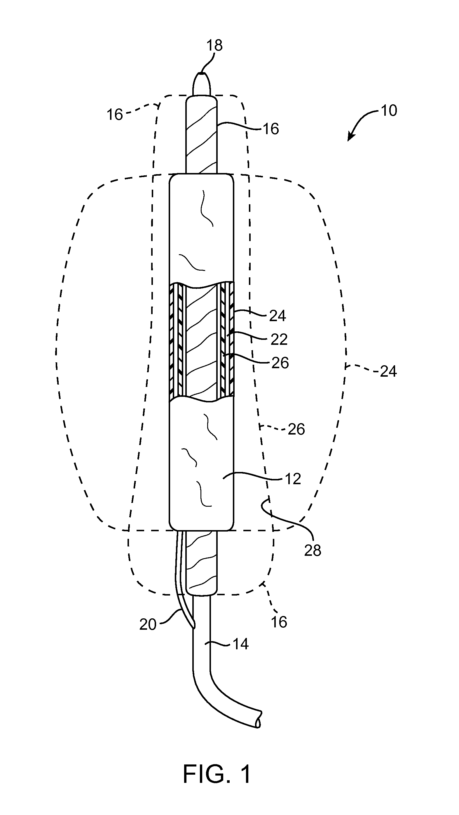
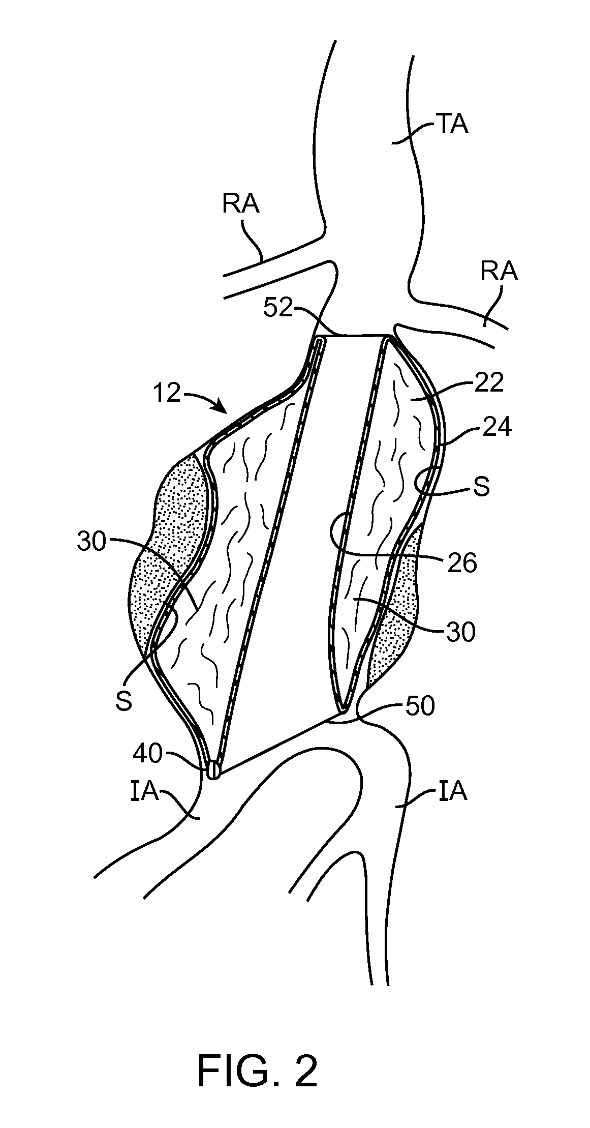
[0043]Embodiments described relate to an aneurysm treatment system comprising a filling structure having a fillable space and a membrane that uses a water transport mechanisms, such as an osmosis process, to adjust the volume of fluid in the fillable space of the filling structure deployed in the aneurysm. By allowing the volume of a fillable space of the filling structure to increase (or decrease) through transport of a fluid through the membrane, such as by diffusion of water vapor through the membrane, the system may accommodate changes in the size or shape of the aneurysm over time. In a preferred embodiment, the water transport occurs through osmosis. In osmosis, which is sometimes referred to as “forward osmosis,” a semi-permeable membrane is used to attract substantially pure water into a solution with a relatively high osmotic pressure from a solution having a relatively low osmotic pressure. In one embodiment, the fillable space of the filling structure is filled with a sol...


PUM


Abstract

Aneurysms are treated by filling at least one double-walled filling structure with a filling medium within the aneurysm, such as filling structures having a membrane that allows water molecules to permeate across the membrane in response to a water potential differential across the membrane. The transport of fluid across the membrane allows the bag to expand or shrink to accommodate changes in the size or shape of the aneurysm, thereby maintaining a seal between the filling structure against the vessel wall and maintaining apposition of the filling structure against the inside surface of the aneurysm. Transport of water molecules into or out of the filling structure is controlled by adjusting for the osmolarity of the filling fluid medium. The filling structures may be delivered over balloon deployment mechanisms in order to shape occlude the aneurysm and open a tubular lumen for flow of blood through the filling structure.

Description

CROSS-REFERENCES TO RELATED APPLICATIONS[0001]The present application is a non-provisional of, and claims the benefit of U.S. Provisional Patent Application No. 61 / 434,954, filed Jan. 21, 2011, the entire contents of which are incorporated herein by reference.[0002]The present application is generally related to the following applications: U.S. application Ser. No. 11 / 187,471 now U.S. Pat. No. 7,530,988, filed on Jul. 22, 2005, U.S. application Ser. No. 11 / 413,460, filed on Apr. 28, 2006, provisional U.S. Application No. 60 / 589,850, filed on Jul. 22, 2004, provisional U.S. Application No. 60 / 675,158, filed on Apr. 28, 2005, and provisional U.S. Application No. 60 / 736,602, filed on Nov. 14, 2005, the full disclosures of which are incorporated herein by reference.BACKGROUND OF THE INVENTION[0003]1. Field of the Invention[0004]The present invention relates generally to medical apparatus and methods for treatment. More particularly, the present invention relates to expandable prosthesis...

Claims


Application Information

Patent Timeline
Patent Type & Authority Applications(United States)
IPC IPC(8): A61M29/00
CPCA61B17/12118A61B17/12136A61B17/12195A61F2/07A61F2230/0034A61F2250/0003A61F2/90A61F2002/075A61F2002/077
Inventor KARWA, ANUPAMAGANPATH, RAJ P.COLTON, CLARK K.RAO, K.T. VENKATESWARA
Owner ENDOLOGIX LLC
Why Eureka
Try Eureka