
Method for minimizing productivity loss while using a manufacturing scheduler

a technology of manufacturing scheduler and productivity loss, which is applied in the direction of adaptive control, process and machine control, instruments, etc., can solve the problems of increasing the rate at which products may become obsolete, tools and resources, of course, are subject to normal wear or periodic maintenance and upgrades,

Inactive Publication Date: 2012-08-09
GLOBALFOUNDRIES INC
View PDF6 Cites 6 Cited by
  • Summary
  • Abstract
  • Description
  • Claims
  • Application Information

AI Technical Summary

Benefits of technology

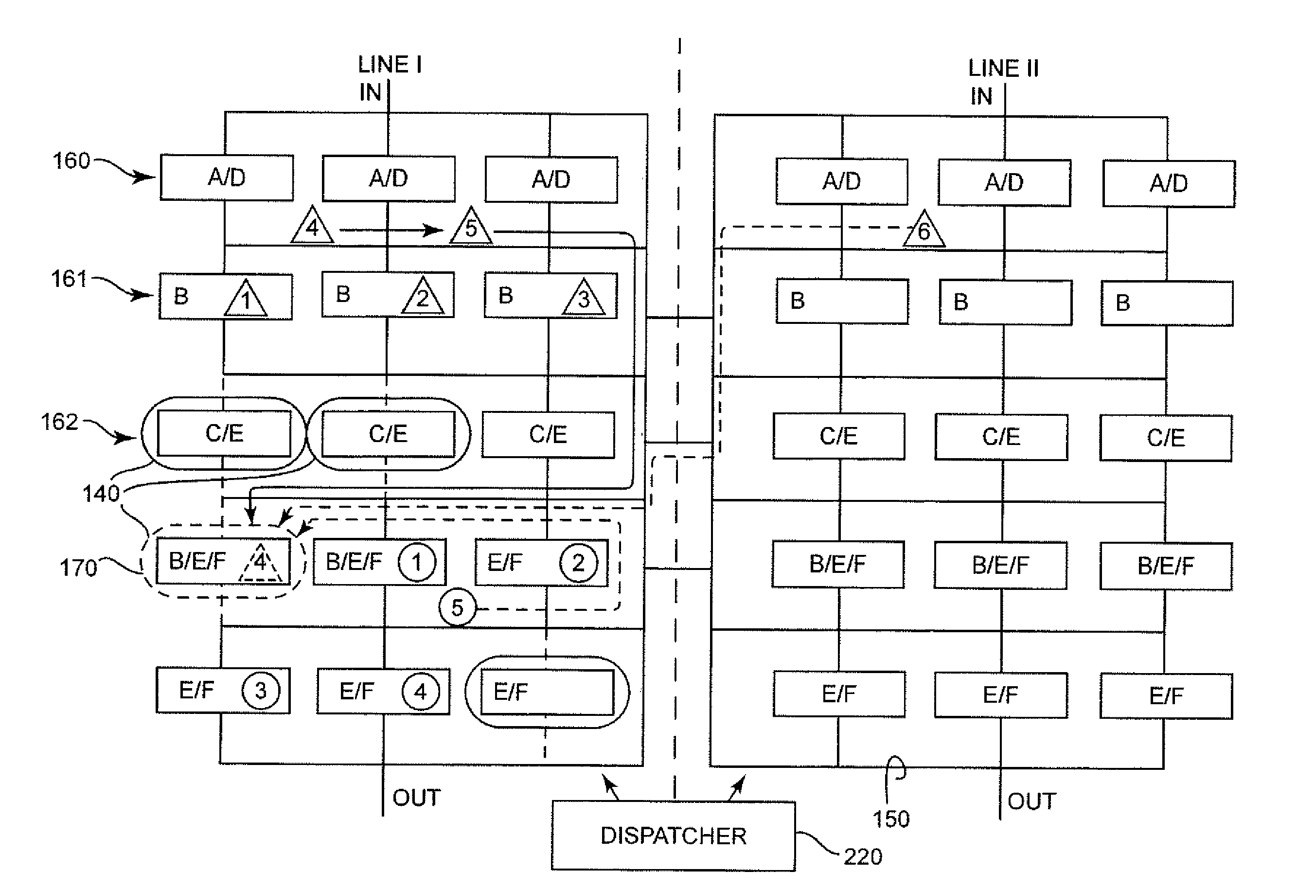
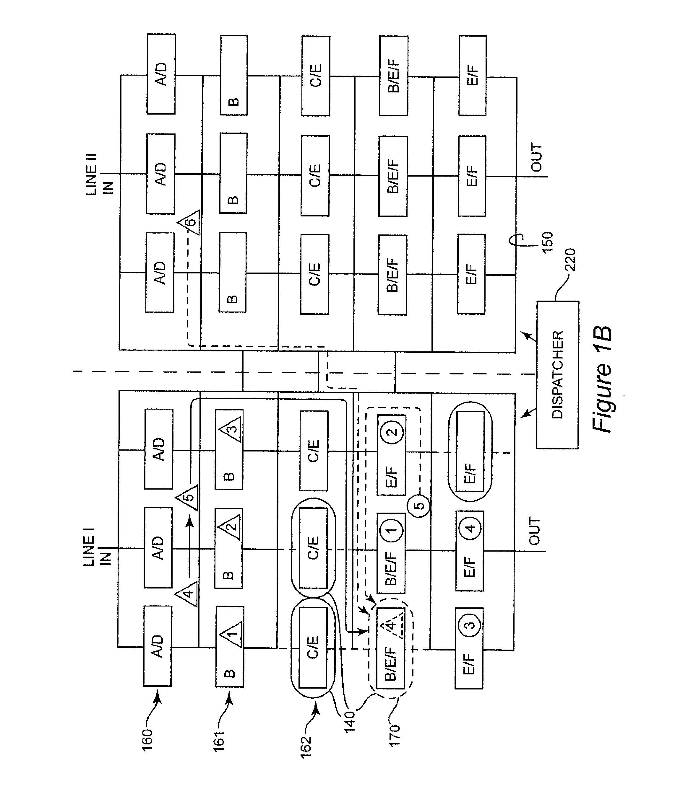
The present invention provides an apparatus and method for utilizing available tools and resources in a manufacturing environment through a real-time manufacturing execution system (MES). The method includes steps of forming a schedule for allocation of tools or resources, detecting availability of a tool or resource, determining work in progress that can be performed by the tool or resource, and dispatching items, in real-time, to the newly available tool or resource to perform a portion of work in progress independently of and consistent with the schedule segment. The manufacturing system includes a MES for monitoring available tools or resources and a dispatcher for dispatching items to the available tool or resource independently of and consistent with the schedule segments. The technical effect of the invention is to maximize utilization of tools or resources, improve manufacturing efficiency, and reduce manufacturing costs.

Problems solved by technology

At the present time, developments in technology have led to an increase of average complexity of products while increasing the rate at which products may become obsolete.
Tools and resources, of course, are subject to normal wear or needs for periodic maintenance and upgrades as well as being subject to unanticipated damage or malfunctions that require the tools or resources to be taken off-line, sometimes referred to as being “down”.
Thus, if a previously unavailable tool or resource becomes available after scheduling for a period of manufacturing has begun, it will not be seen as being available until the start of scheduling for the next subsequent period of manufacturing.
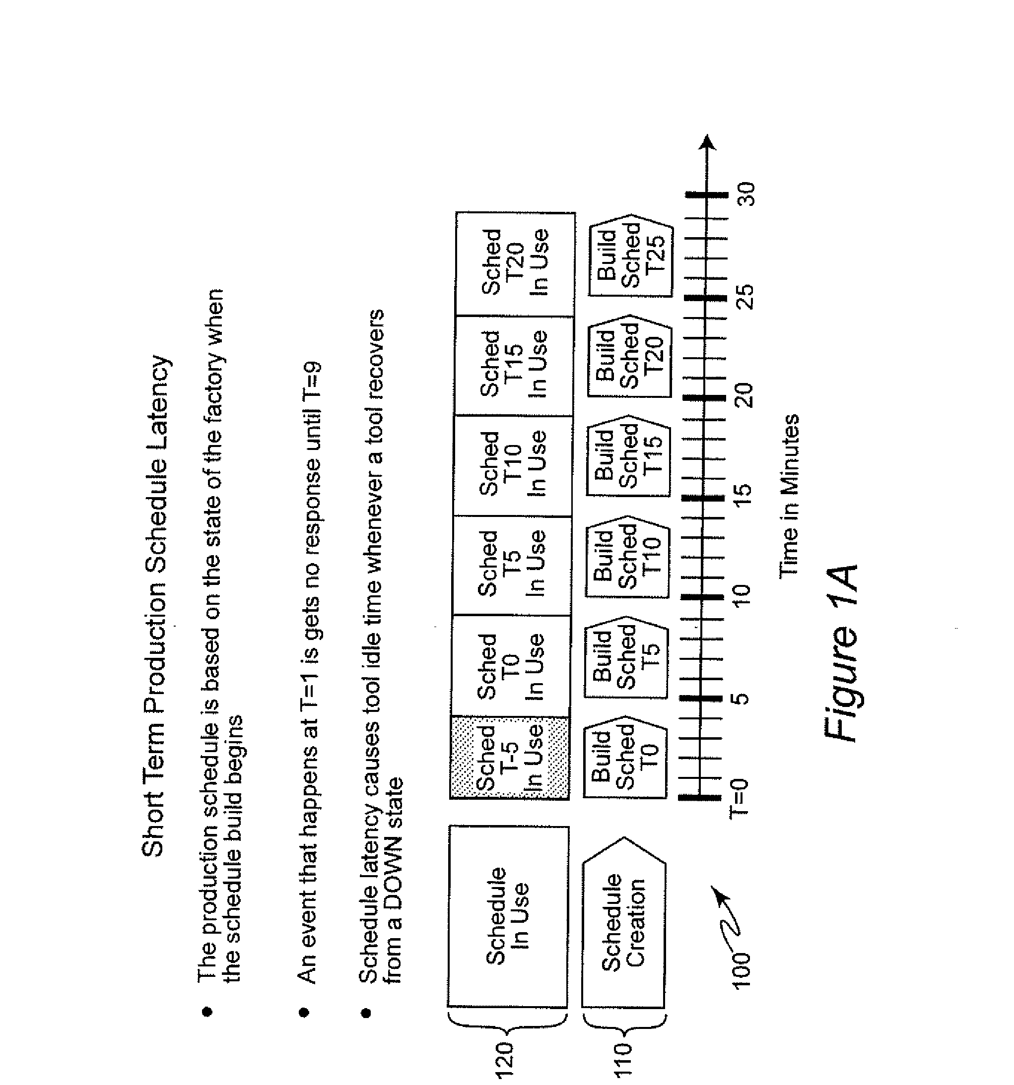
This delay is referred to as latency and results in the tool or resource not being productively utilized for a period of time and may compromise manufacturing throughput.
However, such an approach is not efficient or particularly effective since it requires time for modification of an existing schedule and implementation of the modified schedule to include activities associated with inclusion of the tool or resource in the schedule which may already be critical.

Method used


Image

  • Method for minimizing productivity loss while using a manufacturing scheduler
  • Method for minimizing productivity loss while using a manufacturing scheduler
  • Method for minimizing productivity loss while using a manufacturing scheduler

Examples


Embodiment Construction

[0017]Referring now to the drawings, and more particularly to FIG. 1A, there is shown an exemplary time line 100 useful for conveying an understanding of scheduling latency to which the invention is directed. In FIG. 1A, the time scale is arbitrarily scaled in minutes as may be appropriate for highly automated high speed assembly or manufacturing procedures (or even data processing procedures which are preferentially performed on potentially specially adapted general purpose processors and / or special purpose processors, often in a pipelined fashion similar to a manufacturing line) while a time scale on the order of days or weeks may be more appropriate to heavy machinery or the like. For simplicity of illustration, the building of schedules 110 and the use of the schedules 120 so developed are performed incrementally and for equal five minute periods of time. (However, it is to be understood that such time periods may be of any duration and need not be equal.) For example, as illust...


PUM


Abstract

Tools and / or resources which newly become available to a re-entrant flow manufacturing line, data processing pipeline or the like are allocated in substantially real time to processing operations independent of and consistent with a scheduling segment previously generated by dispatching items such as workpieces or data to tools and / or resources of a manufacturing line until the newly available tool or resource can be conveniently included in a subsequently generated schedule segment in order to avoid productivity loss due to schedule latency. Items can be dispatched in a priority order to accelerate completion of processing. A schedule segment including the newly available tool or resource can be facilitated by merging allocations of a real time dispatch list with allocations of a dispatch list corresponding to a previously generated schedule segment.

Description

BACKGROUND OF THE INVENTION[0001]1. Field of the Invention[0002]The present invention generally relates to the manufacturing of a product using a scheduler for dispatching of lots of products being manufactured to tools and other resources to be used in the manufacturing process and, more particularly, to maximize throughput of all available tools and resources.[0003]2. Description of the Prior Art[0004]The manufacturing of products is a major sector of the economy of many countries of the world and a wide variety of new products are developed and introduced annually. At the present time, developments in technology have led to an increase of average complexity of products while increasing the rate at which products may become obsolete. Therefore, manufacturing infrastructure such as processing pipelines, assembly lines and the like typically comprise tools and resources which are more generalized than in the past such that they can be used to carry out alternative processes and perf...

Claims


Application Information

Patent Timeline
Patent Type & Authority Applications(United States)
IPC IPC(8): G06F19/00
CPCG06Q50/04G06Q10/06Y02P90/30
Inventor BURDA, RICHARD G.KENT, HEATH C.
Owner GLOBALFOUNDRIES INC
Learn More