Device for densely loading a divided solid into a chamber

a technology of divided solids and chambers, which is applied in the direction of liquid bottling, packaging goods types, special packaging, etc., can solve the problems of not being able to independently adjust parameters, devices less suited to loading the holds of ships such as bulk carriers, and endanger the stability of ships

Inactive Publication Date: 2012-08-16
TOTAL RAFFINAGE MARKETING
View PDF28 Cites 17 Cited by
  • Summary
  • Abstract
  • Description
  • Claims
  • Application Information

AI Technical Summary

Benefits of technology

[0019]A main object of the present invention is to overcome the disadvantages of the loading devices known from the prior art by providing a dense loading device that offers greater flexibility in the adjustment of the different parameters that affect the quality and uniformity of the distribution of the particles of a divided solid, whilst allowing high loading rates to be achieved.
[0020]Another object of the present invention is to optimize the density of the loading, the increased mass transported within a predefined volume having obvious advantages from an economic and environmental point of view.
[0022]By virtue of these features, the device according to the invention has operating conditions which can be adjusted precisely depending on the geometry of the chamber to be loaded, which incidentally makes it possible to meet the required filling conditions for loading bulk carriers and at a sufficient rate.
[0027]The density of the loading can thus be optimized. Consequently, the same ship can transport a larger quantity of divided solid on each journey compared with the loading methods from the prior art, affording certain advantages from an economical and environmental point of view.

Problems solved by technology

Consequently, it is not possible to independently adjust the parameters that allow the mode of operation to be adjusted according to the geometry of the chamber to be filled with divided solid.
However, these devices are less suited to loading the holds of ships such as bulk carriers.
The traditional bulk loading of ships transporting cereals can endanger the stability of the ships when at sea.
Even if the hold is completely filled with cargo, the pitching and yawing of the ship when it is sailing cause the grains to settle and create a gap between the bed of grains and the top of the hold.
Even if dockers mechanically level the cargo, this settling when at sea cannot be avoided and can endanger the integrity of the ship, the crew and the cargo.
These movements of the grains resulting from the listing can cause large shifts in the center of gravity of the ship and endanger its stability.
In order to limit this phenomenon, responsible for the capsizing of many ships, the loading of cereals has been subject to special regulations with a view to reducing the risks of the cargo being displaced but which cannot remove these risks altogether.
The devices mentioned above in connection with the loading of chemical reactors generally do not allow such rates to be achieved.
However, these shiploaders are not appropriate for the geometries of all the holds of bulk carriers.
Furthermore, none of the abovementioned devices allow the density of the loading of the grains to be optimized and hence completely obviate the problem of the stability of the ships.
When catalyst is loaded into a chamber such as a reactor, constraints connected with the anisotropy of the particles of catalyst can result in deviations in the loading profile (appearance of the exposed surface of the catalyst bed, for example the observation of the presence of bumps and craters) from a theoretical flat loading profile.
If the positioning of the particles of catalyst on the surface of the catalyst bed is not homogeneous during loading, this can cause the appearance of the phenomenon of channeling during operation, in other words favored passages which impair the effectiveness of the desired conversion.
There may be many consequences, including an increase in the rate of piercing of the catalyst bed, a reduction in the conversion efficiency, a change in the pressure drop, irregularities in the temperature profile during operation, and premature ageing of the catalyst.
As a consequence, a more frequently replacement of the catalyst bed may be observed, as well as an increase of the catalyst costs, of the maintenance costs, of the rate of use of the industrial equipment, and there may be a further economic loss connected with the poor quality of the products resulting from the conversion, the value of said products consequently being reduced.
This phenomenon is associated with a more rapid ageing of the equipment, connected with a greater proportion of catalyst fines that will erode the walls of the equipment, cause clogging, and increase the pace of corrosion.

Method used


Image

  • Device for densely loading a divided solid into a chamber
  • Device for densely loading a divided solid into a chamber
  • Device for densely loading a divided solid into a chamber

Examples


embodiment (

EMBODIMENT(S) OF THE INVENTION

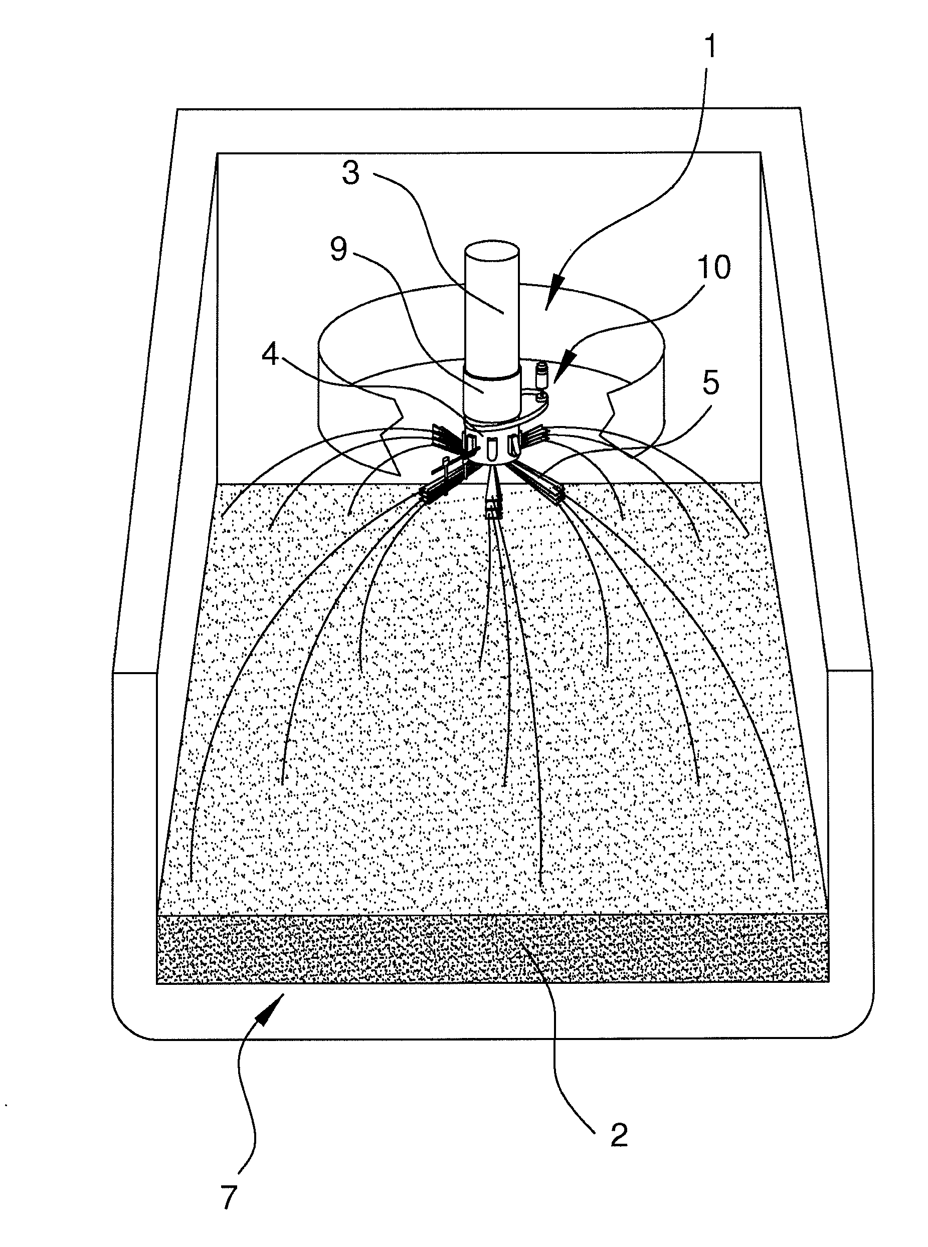
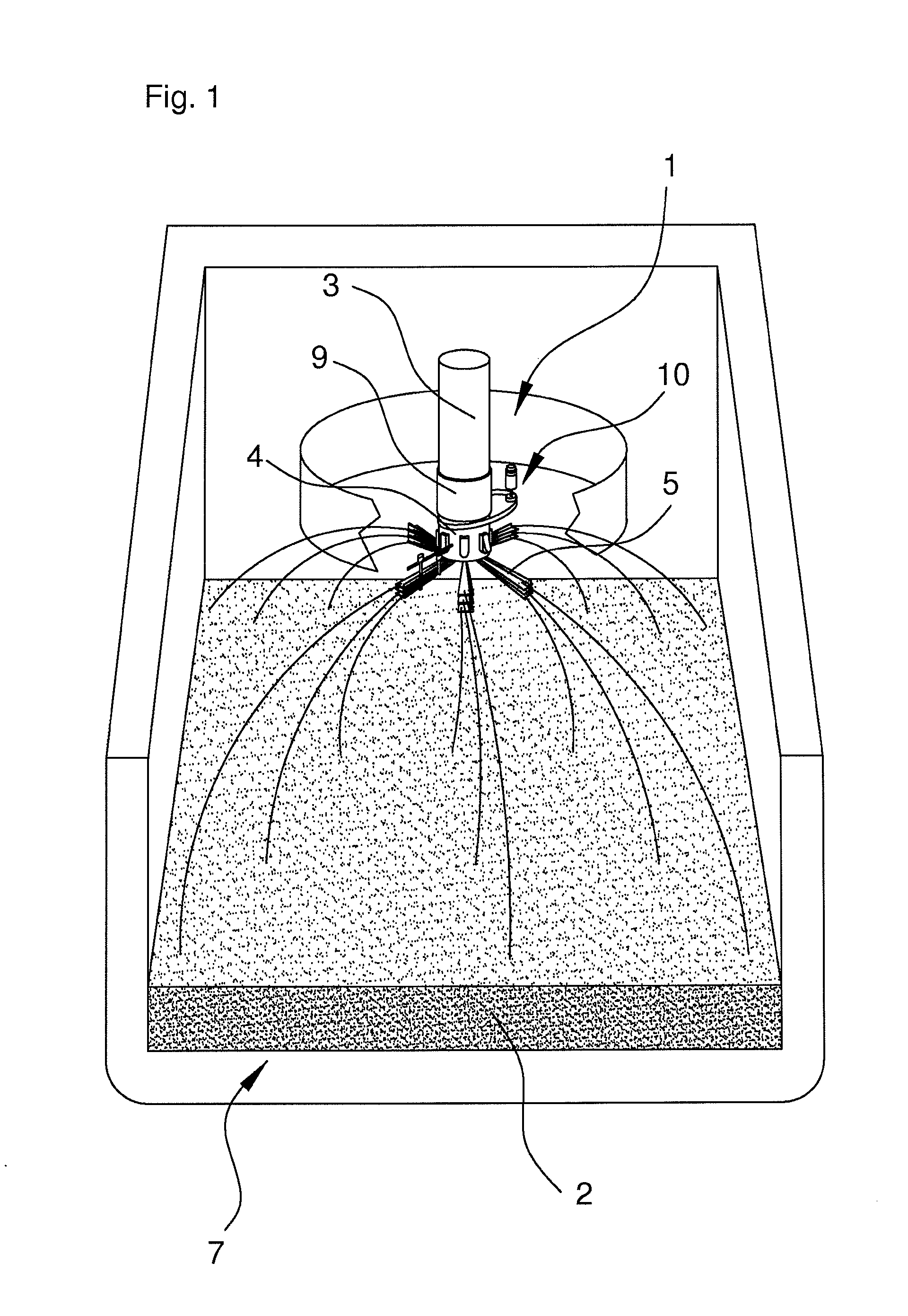
[0033]FIG. 1 illustrates, by way of non-limiting example and schematically, the principle of the operation of the dense loading device according to the present invention.

[0034]The dense loading device 1 is supplied with cereal grains 2 from a primary storage site, through a pipe, generally at a fixed rate, opening out into a chute 3. The use of a conventional buffer hopper between the pipe and the chute can be provided without going beyond the scope of the invention.

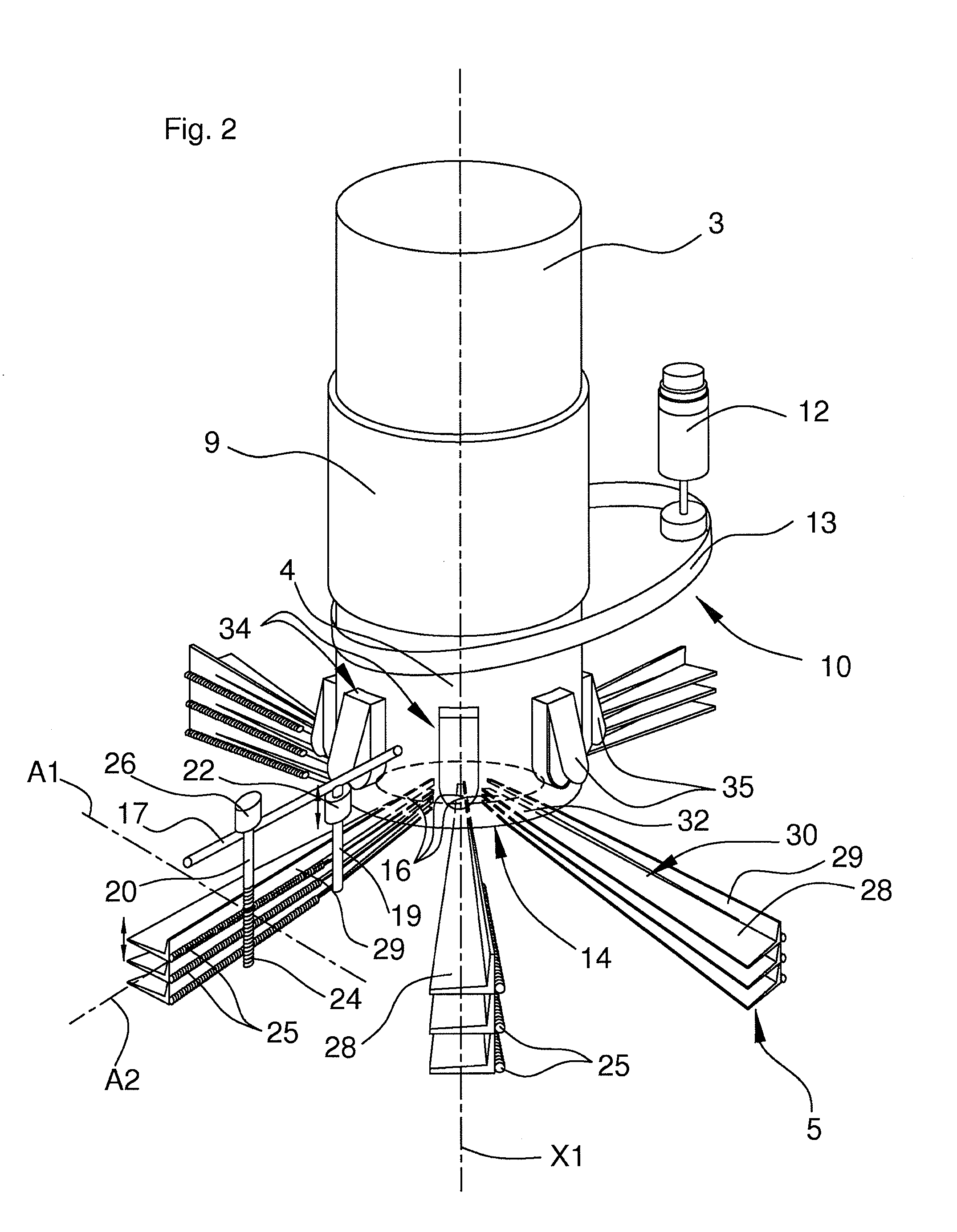
[0035]The loading device 1, arranged in alignment with the chute 3, comprises a rotating member 4, crammed full of grains from the pipe, having a plurality of openings (described in more detail in relation to FIG. 2) intended to homogeneously distribute the grains over a set of deflecting elements 5.

[0036]The stream of grains must preferably be broken up as much as possible in order to optimize the distribution of the grains before they are acted on by the deflecting elements. The grains the...


PUM

PropertyMeasurementUnit
angleaaaaaaaaaa
surface areaaaaaaaaaaa
rotational speedaaaaaaaaaa

Abstract

A device for densely loading a divided solid into a chamber, intended to interact with a divided-solid supply device arranged to release the divided solid above an access to the chamber. The loading device contains a shaft rotated about an axis X1 at an adjustable rotational speed, a plurality of deflecting elements rigidly connected in rotation with the shaft, the deflecting elements having an angle, relative to the shaft, which is separately adjustable from the rotational speed of the latter. According to a preferred embodiment, the shaft is hollow in order to define a passage for the divided solid, at least some of the deflecting element having an end arranged at a distance from the axis X1 that is smaller than the distance separating the axis X1 from the hollow shaft.

Description

BACKGROUND OF THE INVENTION[0001]The present invention relates to a device for densely loading a divided solid into a chamber, intended to interact with a divided-solid supply device designed so as to release the divided solid above an access point to the chamber.[0002]Within the scope of the present disclosure, a divided solid is understood to be a solid in the form of grains or particles, such as, for example, cereal grains in the cereals transportation or storage sector, catalyst pellets in the chemical industry, or fertilizer or wood pellets.[0003]More precisely, the loading device according to the invention is preferably of the type comprising a shaft, driven in rotation about an axis X1 at an adjustable rotational speed, and a plurality of deflecting elements that are integral in rotation with the shaft. Thus, when it falls onto the deflecting elements, the divided solid is deflected so as to be distributed more or less uniformly over the whole surface of the chamber into whic...

Claims


Application Information

Patent Timeline
Patent Type & Authority Applications(United States)
IPC IPC(8): B65B1/04
CPCB01J8/002B65G69/0458B01J8/003
Inventor GIRARD, OLIVIERVIAL, ROMAIN
Owner TOTAL RAFFINAGE MARKETING
Why Eureka
Try Eureka