Method for setting the clamping force of a hydraulically supported electric motor-driven parking brake

a technology of hydraulically supported electric motors and parking brakes, which is applied in the direction of mechanical equipment, braking systems, transportation and packaging, etc., can solve the problems of inability to determine the total clamping force relatively imprecisely, and the design of electric motors that are more weak

Active Publication Date: 2012-08-16
ROBERT BOSCH GMBH
View PDF9 Cites 27 Cited by
  • Summary
  • Abstract
  • Description
  • Claims
  • Application Information

AI Technical Summary

Benefits of technology

[0008]The exemplary embodiments and / or exemplary methods of the present invention provide that a method for setting the clamping force (F) exerted by a parking brake be implemented, in which in an operating phase, in which both the electric motor and also the actuator (e.g., a hydraulic pump) of a second brake device simultaneously exert force; the power consumption (i) of the electric motor-driven brake device is regulated to an essentially constant value. This is because the torque of the electric motor and therefore also the speed are essentially constant in the case of constant power consumption. The distance covered by the brake piston may be calculated very precisely from the constant speed (in consideration of a transmission ratio). A desired clamping force which rises approximately proportionally to the distance may thus be set precisely. The current regulation therefore has the advantage that the clamping force may be set very precisely without requiring additional sensors.
[0009]According to a specific embodiment of the present invention, a current regulator is provided, which uses the actuator of the second (e.g., hydraulic) brake device as a final control element. Through variation of the hydraulic pressure, it is possible to relieve the electric motor of the parking brake to different extents. The drive torque of the electric motor and therefore also its power consumption may therefore be kept at an essentially constant value.

Problems solved by technology

In addition, it is understood that there are parking brake systems in which the electric motors are designed more weakly.
In the last-mentioned APB systems having hydraulic support, however, it is problematic that the total clamping force can only be determined relatively imprecisely or only with high sensory outlay.

Method used


Image

  • Method for setting the clamping force of a hydraulically supported electric motor-driven parking brake
  • Method for setting the clamping force of a hydraulically supported electric motor-driven parking brake
  • Method for setting the clamping force of a hydraulically supported electric motor-driven parking brake

Examples


Embodiment Construction

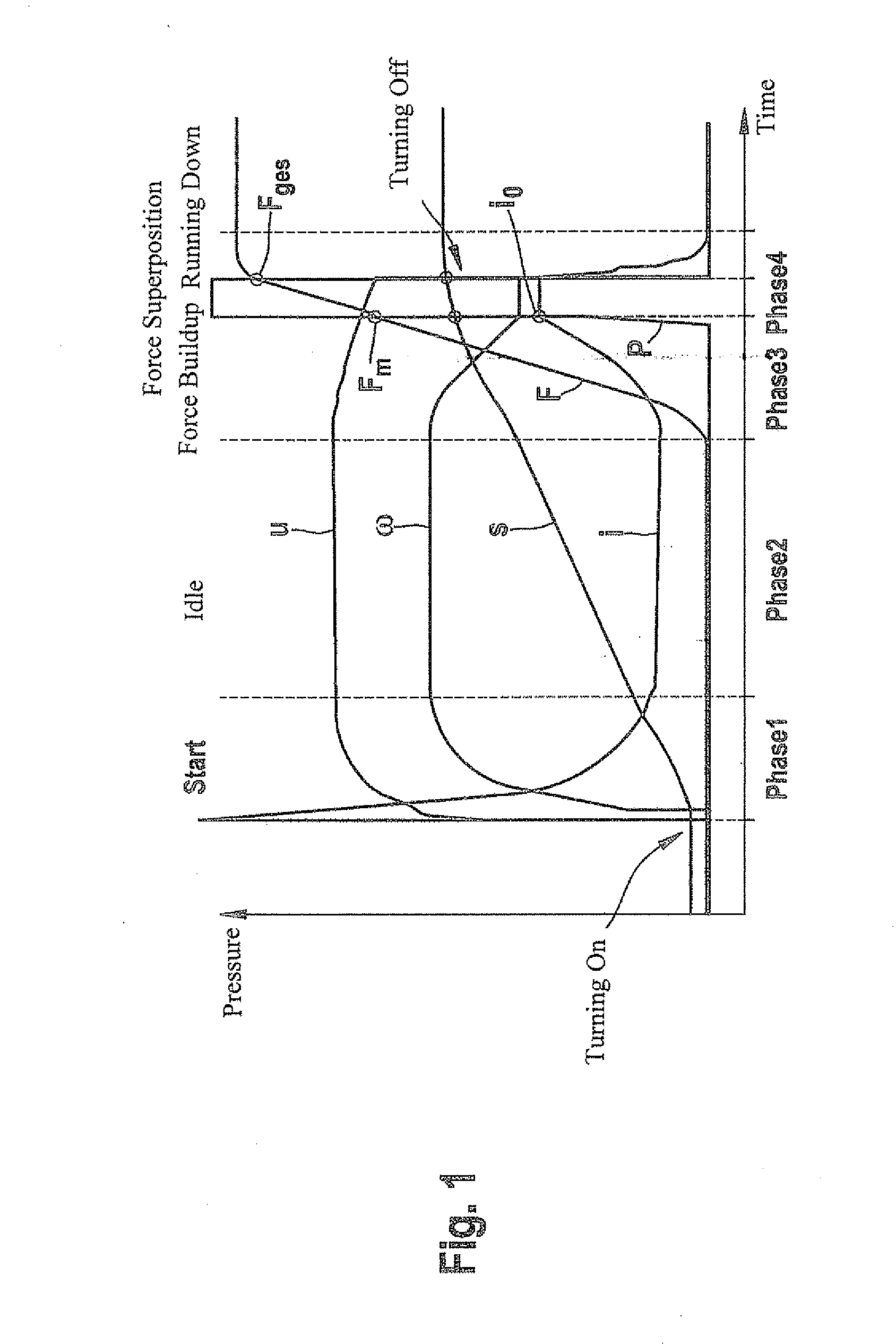
[0020]FIG. 1 shows the time curve of various operating variables of a parking brake during an application procedure of the brake. The application procedure may essentially be divided into four phases:

[0021]At the beginning of a phase 1, an application command is recognized and electric motor 1 installed on the wheel brake is turned on. When electric motor 1 is turned on, a starting current peak is recognizable. Current i of electric motor 1 then drops in the further curve until an idle current results at the end of phase 1. Speed ω of electric motor 1 rises in phase 1, i.e., electric motor 1 is accelerated. At the end of phase 1, speed ω of electric motor 1 reaches an idle speed. Voltage u of electric motor 1 also rises. An idle voltage results at the end of phase 1. A nut is moved in the direction of a brake piston of the wheel brake by the rotation of a spindle. Since the nut is not yet in contact with the piston floor, clamping force F is equal to zero. Pressure p of hydraulic pu...


PUM


Abstract

A method for setting the clamping force acting on a wheel brake, a part of the clamping force being provided using an electromechanical brake device and simultaneously another part of the clamping force being provided using a hydraulic brake device. During an application procedure, the power consumption of the electric motor-driven brake device is regulated to an essentially constant value in an operating phase (phase 4), in which both brake devices simultaneously exert force, so as to set the clamping force of the parking brake very precisely.

Description

FIELD OF THE INVENTION[0001]The present invention relates to a method for setting the clamping force exerted by a hydraulically supported parking brake.BACKGROUND INFORMATION[0002]Automatic parking brakes (APB) may include an operating element, such as a button, using which the parking brake may be locked or disengaged. Upon operation of the operating element, a control unit connected thereto recognizes the parking brake command and accordingly activates a final control element, such as a hydraulic pump or an electric motor, to build up brake force on the wheels of the vehicle or to disengage the brake.[0003]It is understood that there are automatic parking brakes (APB) in which electric motors are located directly on the brake caliper of the wheel brakes (so-called “motor-on-caliper”). The electric motors act via a gearing, such as a spindle drive, directly on the brake piston of the hydraulic brake system and therefore can apply or disengage the service brake. The electric motors ...

Claims


Application Information

Patent Timeline
Patent Type & Authority Applications(United States)
IPC IPC(8): B60T13/58B60T13/74F16D65/18
CPCB60T13/588F16D2121/24F16D2121/02B60T13/746
Inventor BAEHRLE-MILLER, FRANKBLATTERT, DIETERBLESSING, PETER
Owner ROBERT BOSCH GMBH
Why Eureka
Try Eureka