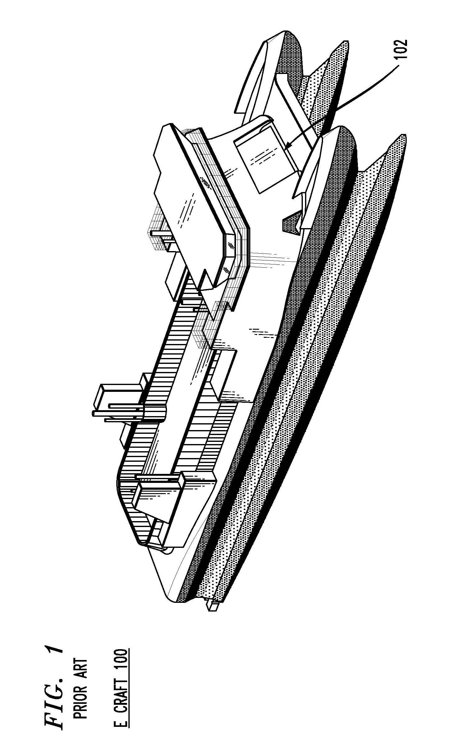
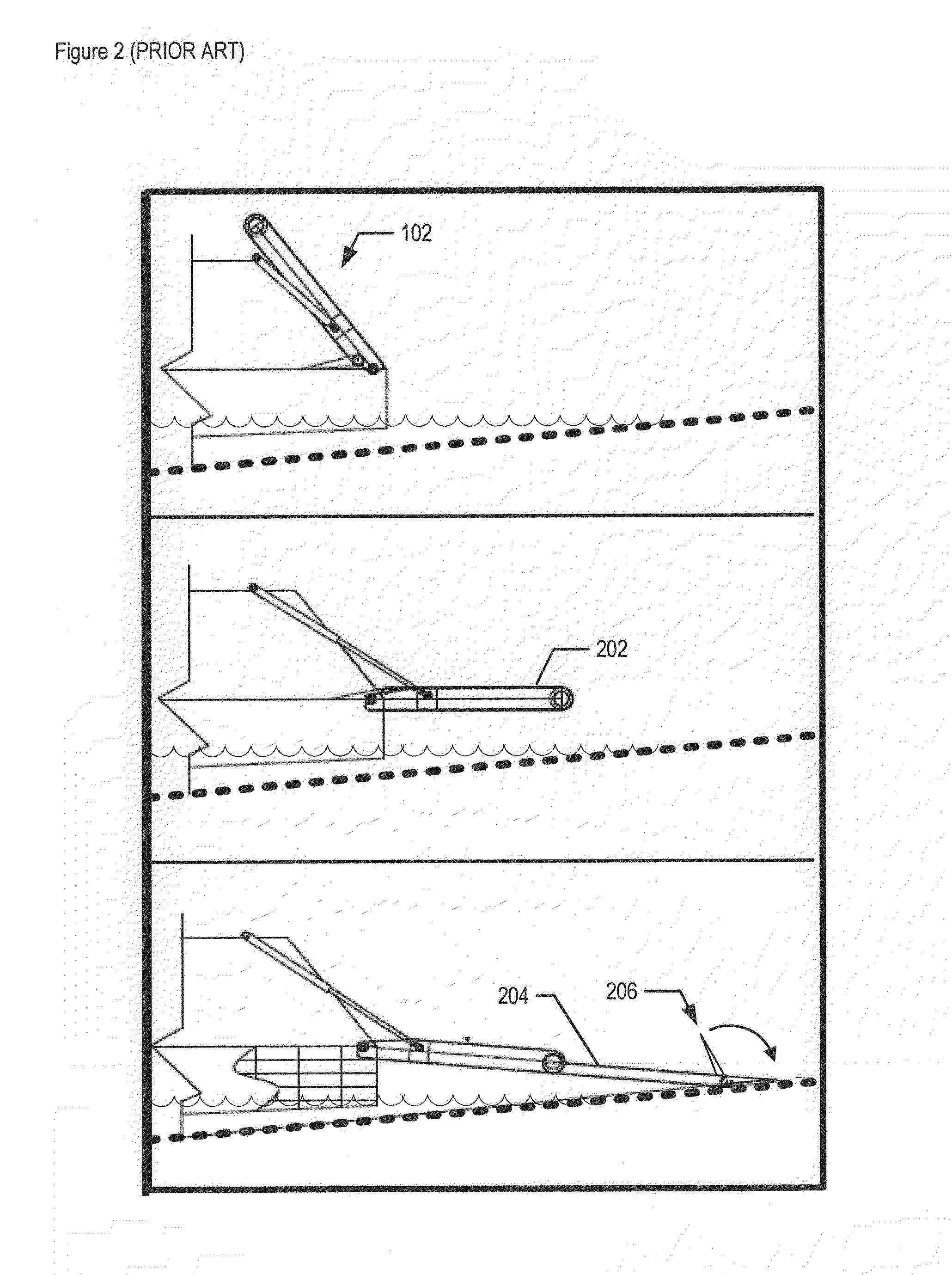
[0010]has reduced maintenance needs, which is particularly advantageous since the E-craft is likely to be deployed in environments / situations that make maintenance impractical for extended periods; and
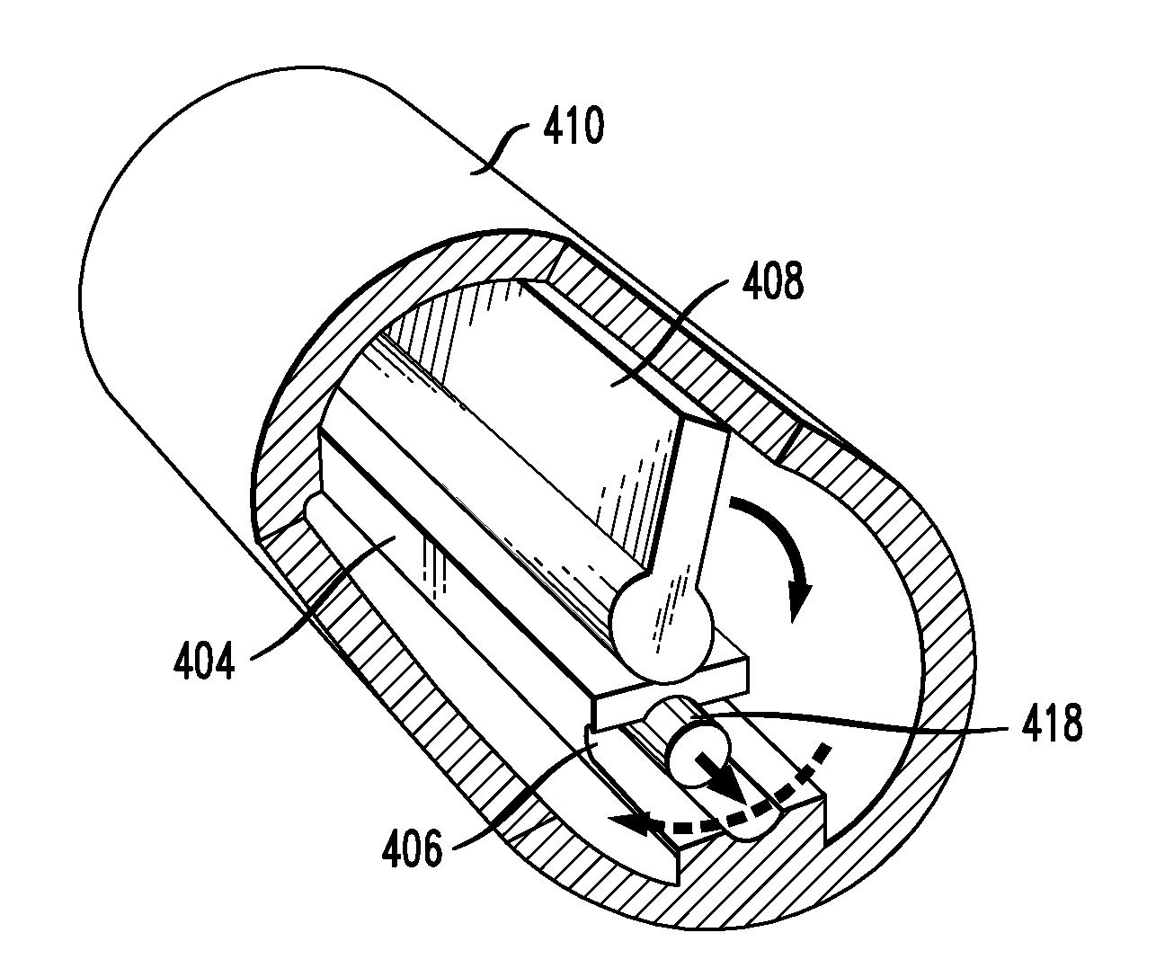
[0012]The illustrative embodiment of the present invention is a ramp comprising a high-torque damper with variable speed control (hereinafter “damper”). In the illustrative embodiment, the damper couples to an apron that is at the end of a ramp. The damper has a
large range of motion and controls the speed of rotation of the apron. In effect, the damper according to the illustrative embodiment acts as a rotational axle between the apron and the predecessor stage of the ramp. The present invention is not limited to aprons and ramps, however. For example, the damper described herein can be used to provide an improved tailgate, wherein the damper controls the tailgate's rotational speed when it is to be opened for loading cargo into the rear of a vehicle.
[0014]The rate of flow through the housing's interior is determined by (1) the rheological properties (e.g.,
viscosity, etc.) of the fluid and (2) the size of the orifice. In regards to the rheological properties, as the
viscosity of the fluid decreases, resistance to flow decreases and the viscous drag on an object immersed in the fluid decreases; as the
viscosity of the fluid increases, the resistance to flow increases and the viscous drag on an object immersed in the fluid increases. For an orifice of a given size, increased viscosity results in a reduced rate of flow of the fluid and a reduction in the speed at which the blade (see above) moves through the fluid. Thus, an increase in viscosity slows the shaft's rotational speed. In regards to the size of the orifice, a smaller orifice increases the drag upon the flow of fluid, thereby slowing the shaft's rotational speed. Conversely, a larger orifice decreases drag and enables the shaft to rotate faster. In this way, viscosity and orifice size affect the speed of rotation of the apron or of any structure that is operatively coupled to the damper.
[0018](iii) the fluid that flows through the orifice between the chambers is selected such that its viscosity decreases with an increase in temperature.Ordinarily, an increase in ambient temperature (and, hence, in the temperature of the fluid in the chambers) results in an increase in flow through the orifice. This ultimately results in an increase in the rotational speed of the apron. But in the illustrative embodiment, when temperature increases, the elongating thermal compensator will decrease the size of the orifice and thus reduce the rate of flow of the fluid. With an appropriately designed thermal compensator (i.e., accounting for the rheological characteristics of the fluid), the increase in drag resulting from the decrease in orifice size offsets (to some degree) the decrease in drag due to the decrease in viscosity. The result is that the flow rate through the orifice changes less than it otherwise would. Thus, because of the thermal compensator, the rotational speed available from the damper remains relatively unchanged, i.e., substantially constant, over the design temperature range, or at least, exhibits less change than it would in the absence of the thermal compensator.
[0020]In the illustrative embodiment, the position adjustor is a screw that is coupled to the thermal compensator. Turning the screw in one or the other direction (i.e.,
clockwise or counterclockwise) causes the screw and the thermal compensator to advance or retract relative to the orifice. The position adjustor thus provides a way to calibrate, fine tune, or alter the operation of the thermal compensator. For a theoretically perfect thermal compensator, thermal response of the device is precisely matched to the fluid's viscosity-temperature behavior over the design temperature range such that the resulting change in orifice size maintains a constant rotational speed available from the damper. As such, once a perfect thermal compensator is suitably positioned with respect to the orifice, it need not be moved as long as the temperature remains within the design range. But a “real” thermal compensator is not perfect, and changes in the length of the thermal compensator with temperature will not perfectly correct for changes in
fluid viscosity. To maintain a near constant rotational speed for the apron as temperature changes, the position of the thermal compensator may require slight adjustments to alter the amount by which the orifice is occluded. This is accomplished by the position adjustor. Thus, the position adjustor enables an operator to fine tune the damper's
temperature response for nonlinearities in the thermal compensator's response or for operational temperatures that are out of the design temperature range. Alternatively, by using the position adjustor, an operator can increase or decrease the rotational speed available from the damper from the nominal speed.
[0022]Collectively, the thermal compensator and the position adjustor expand the operational window and versatility of the damper.


