Magnetic tunnel junction with spacer layer for spin torque switched MRAM

Active Publication Date: 2012-08-16
GLOBALFOUNDRIES US INC
View PDF15 Cites 19 Cited by
  • Summary
  • Abstract
  • Description
  • Claims
  • Application Information

AI Technical Summary

Problems solved by technology

However, MTJs made using PMA materials may have a relatively low TMR because of structural and chemical incompatibility between the various material layers that comprise a PMA MTJ.
A relatively low TMR may result in difficulty with read operations in the STT MRAM, as the difference in resistance between the high and low resistance states of the MTJs will also be relatively low.

Method used


Image

  • Magnetic tunnel junction with spacer layer for spin torque switched MRAM
  • Magnetic tunnel junction with spacer layer for spin torque switched MRAM
  • Magnetic tunnel junction with spacer layer for spin torque switched MRAM

Examples


Embodiment Construction

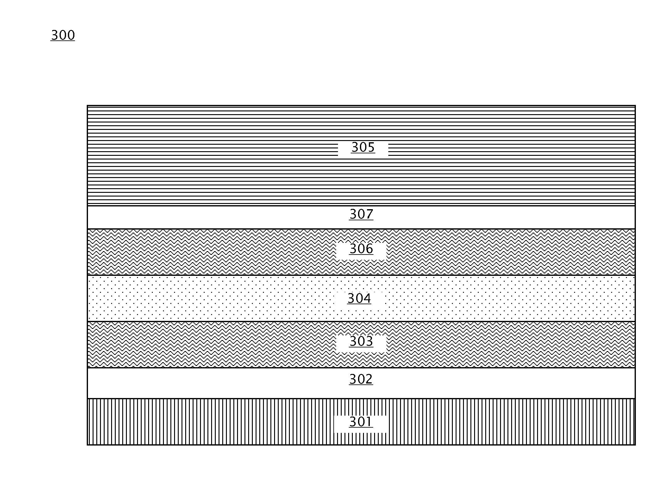
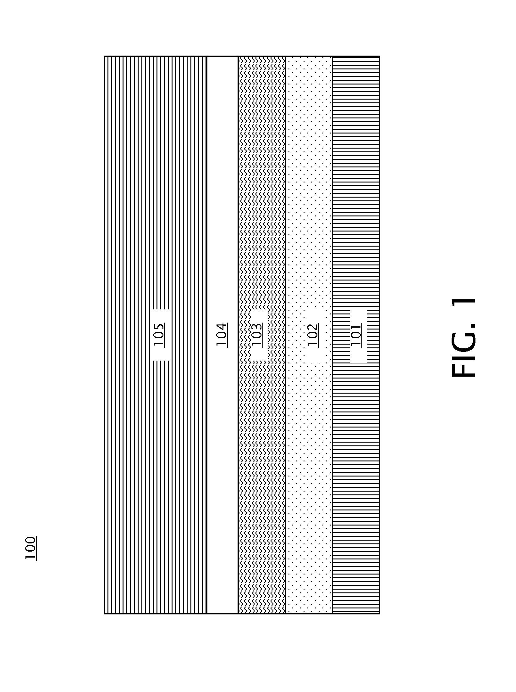
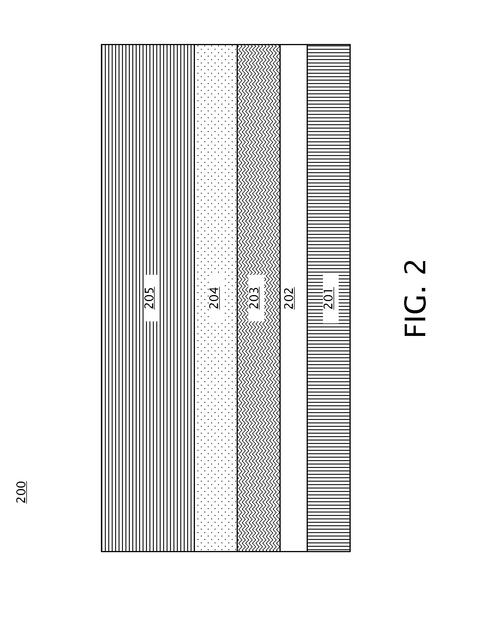
[0014]Embodiments of spacer layers for a MTJ for use in STT MRAM are provided, with exemplary embodiments being discussed below in detail. The spacer layer(s) act to raise the TMR of a PMA MTJ. A spacer layer may be inserted between a free layer and an interfacial layer of an MTJ, or between a fixed layer and an interfacial layer of the MTJ, or in any other appropriate location in the MTJ in various embodiments. An MTJ may include one spacer layer or multiple spacer layers in various embodiments. A MTJ spacer layer may include a single layer of a non-magnetic material, or a relatively thin layer of a magnetic material located between two relatively thin layers of a non-magnetic material. A MTJ spacer layer may be relatively thin (e.g., 20 angstroms or less in some embodiments) to ensure a strong magnetic coupling between the interfacial layer and the free / fixed magnetic layers.

[0015]An MTJ includes a non-magnetic, insulating tunnel barrier layer located between the fixed and free ma...


PUM


Abstract

A magnetic tunnel junction (MTJ) includes first and second magnetic layers; a tunnel barrier located between the first and second magnetic layers; a first spacer layer located between the first magnetic layer and the tunnel barrier, the first spacer layer comprising a non-magnetic material; and a first interfacial layer located between the first spacer layer and the tunnel barrier.

Description

BACKGROUND[0001]This disclosure relates generally to the field of magnetoresistive random access memory (MRAM), and more specifically to spin torque switched (STT) MRAM.[0002]MRAM is a type of solid state memory that uses tunneling magnetoresistance (TMR) to store information. MRAM is made up of an electrically connected array of magnetoresistive memory elements, referred to as magnetic tunnel junctions (MTJs). Each MTJ includes a free layer having a magnetization direction that is variable, and a fixed layer having a magnetization direction that is invariable. The free layer and fixed layer each include a layer of a magnetic material, and are separated by an insulating non-magnetic tunnel barrier. An MTJ stores information by switching the magnetization state of the free layer. When the magnetization direction of the free layer is parallel to the magnetization direction of the fixed layer, the MTJ is in a low resistance state. When the magnetization direction of the free layer is a...

Claims


Application Information

Patent Timeline
IPC IPC(8): H01L29/82
CPCH01L29/82H01L43/08B82Y40/00H01F41/307H01F10/3254H10N50/10
Inventor HU, GUOHAN
Owner GLOBALFOUNDRIES US INC
Why Eureka
Try Eureka