Magneto-resistance effect element and magnetic memory

a technology which is applied in the field of magnetic memory and resistance effect element, can solve the problems of large power consumption, mass storage, and the inability to reduce the cell size to that of a dram (dynamic random access memory) made of semiconductors

Inactive Publication Date: 2006-10-12
KK TOSHIBA
View PDF10 Cites 145 Cited by
  • Summary
  • Abstract
  • Description
  • Claims
  • Application Information

AI Technical Summary

Benefits of technology

[0018] In view of these circumstances, an object of the present invention is to provide a magneto-resi

Problems solved by technology

Regarding a cell size of a memory, however, when an architecture where each memory cell includes a transistor and a TMR element is used, there is such a problem that a size of the cell can not be reduced to that of a DRAM (dynamic random access memory) made of semiconductor or less.
In both the cases, however, since inversion of magnetization of the magnetic recording layer is performed by current magnetic filed due to current pulses at a time of writing in a magnetic recording layer, there is such a problem that power consumption is large, mass storage can not be achieved due to an allowable current density limit in writing f

Method used


Image

  • Magneto-resistance effect element and magnetic memory
  • Magneto-resistance effect element and magnetic memory
  • Magneto-resistance effect element and magnetic memory

Examples


first embodiment

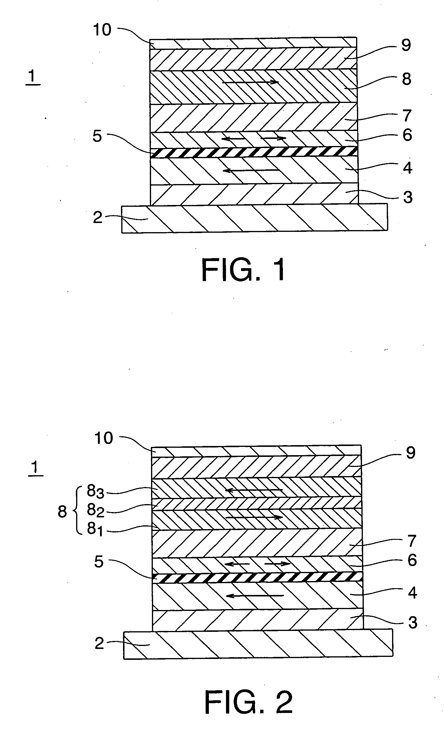
[0068] A magneto-resistance effect element according to a first embodiment of the invention is shown in FIG. 1. A magneto-resistance effect element 1 of the embodiment is provided with a base layer 2 serving as a lower electrode, an anti-ferromagnetic layer 3 provided on the base layer 2, a first magnetization pinned layer 4 which is provided on the anti-ferromagnetic layer 3 and has whose direction of magnetization is pinned; a tunnel barrier layer 5 which is provided on the first magnetization pinned layer 4, a magnetization free layer 6 which is provided on the tunnel barrier layer 5 so as to serve as a magnetic recording layer and whose direction of magnetization is variable, a non-magnetic layer 7 which is provided on the magnetic recording layer 6, a second magnetization pinned layer 8 which is provided on the non-magnetic layer 7 and has pinned magnetization whose direction is different from that of the first magnetization pinned layer 4 by an angle of 180°, an anti-ferromagn...

second embodiment

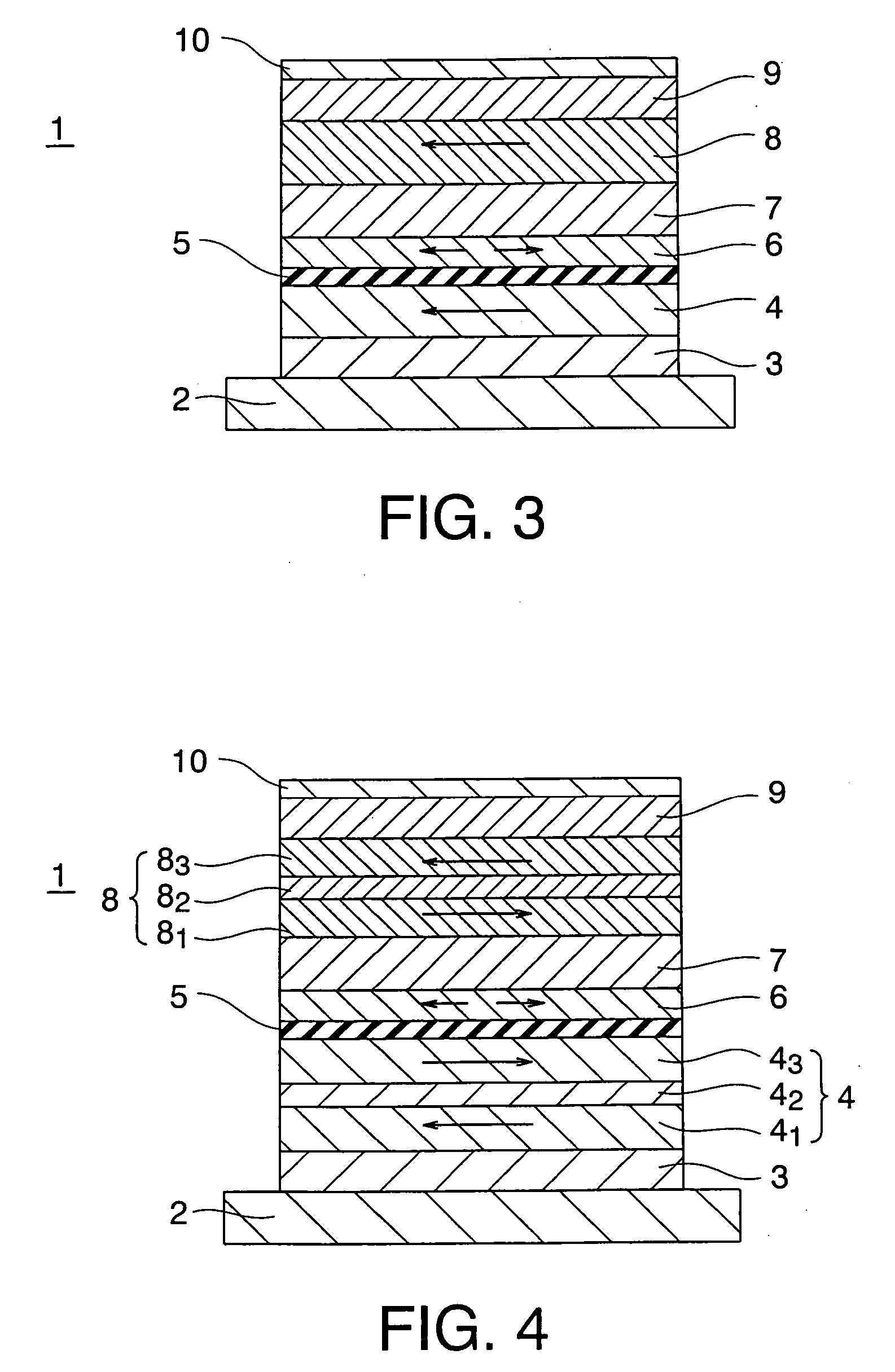
[0078] Next, a magneto-resistance effect element according to a second embodiment of the invention is shown in FIG. 3. A magneto-resistance effect element 1 of the embodiment is configured such that an orientation of magnetization of the second magnetization pinned layer 8 becomes substantially parallel to that of the first magnetization pinned layer 4 in the magneto-resistance effect element according to the first embodiment shown in FIG. 1.

[0079] As the embodiment, the inventors have found that preferable combinations of the non-magnetic layer 7 and the second magnetization pinned layer 8 when orientations of magnetizations of the magnetization pinned layers 4, 8 are substantially parallel include the following combinations of materials. Specifically, when the second magnetization pinned layer 8 is made of Co-rich ferromagnetic material, material for the non-magnetic layer 7 is at least one element selected from the group consisting of Cr, Ir, Mn, V, Rh, and Ru.

[0080] When the s...

third embodiment

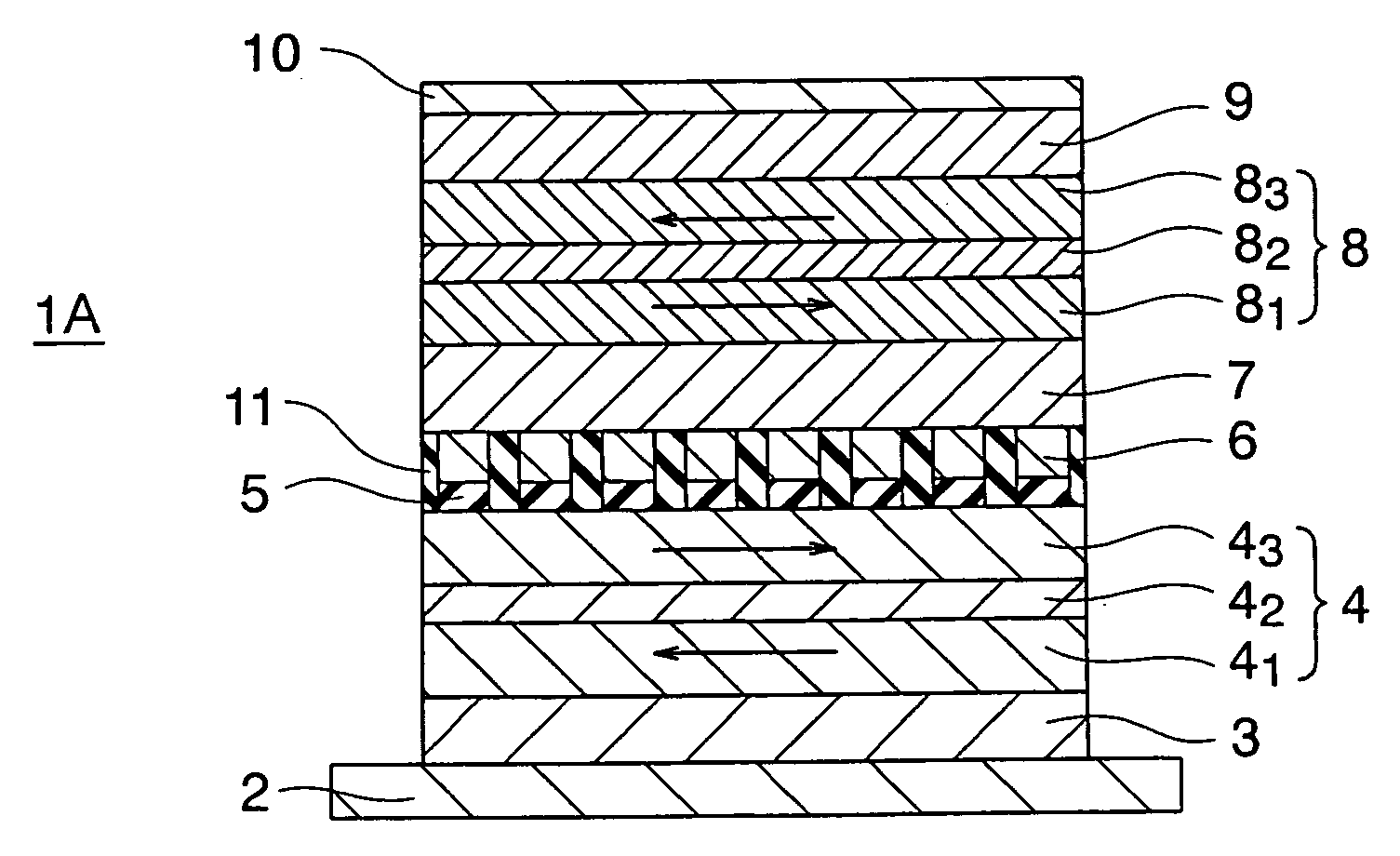
[0083] Next, a magneto-resistance effect element according to a third embodiment of the invention is shown in FIG. 5. In each of the magneto-resistance effect elements according to the first and second embodiments, the tunnel barrier layer 5, the magnetic recording layer 6, and the like were the continuous films. A magneto-resistance effect element 1A according to the embodiment includes a column-shaped stacked structure portion obtained by stacking a tunnel barrier layer 5 and a magnetic recording layer 6 on one another, and it has a configuration that a plurality of the column-shaped stacked structure portions are provided on the first magnetization pinned layer 4 so as to be spaced from one another. The plurality of the column-shaped stacked structure portions are insulated from one another by insulators 11. A non-magnetic layer 7, a second magnetization pinned layer 8, an anti-ferromagnetic layer 9, and an electrode layer 10 are stacked on the column-shaped structure portions. T...


PUM


Abstract

It is possible to reduce a current required for spin injection writing. A magneto-resistance effect element includes: a first magnetization pinned layer; a magnetization free layer; a tunnel barrier layer; a second magnetization pinned layer whose direction of magnetization is pinned to be substantially anti-parallel to the direction of magnetization of the first magnetization pinned layer, and; a non-magnetic layer. When the second magnetization pinned layer is made of ferromagnetic material including Co, material for the non-magnetic layer is metal including at least one element selected from the group consisting of Zr, Hf, Rh, Ag, and Au; when the second magnetization pinned layer is made of ferromagnetic material including Fe, material for the non-magnetic layer is metal including at least one element selected from the group consisting of Rh, Pt, Ir, Al, Ag, and Au; and when the second magnetization pinned layer is made of ferromagnetic material including Ni, material for the non-magnetic layer is metal including at least one element selected from the group consisting of Zr, Hf, Au, and Ag.

Description

CROSS-REFERENCE TO RELATED APPLICATION [0001] This application is based upon and claims the benefit of priority from prior Japanese Patent Application No. 2005-82219 filed on Mar. 22, 2005 in Japan, the entire contents of which are incorporated herein by reference. BACKGROUND OF THE INVENTION [0002] 1. Field of the Invention [0003] The present invention relates to a magneto-resistance effect element and a magnetic memory. [0004] 2. Related Art [0005] It has been proposed that a magneto-resistance effect element using a magnetic material film is used not only for a magnetic head, a magnetic sensor or the like but also for a solid magnetic memory (magnetic random access memory or MRAM). [0006] In recent years, a so-called “tunneling magneto-resistance effect element (TMR) has been proposed as a magneto-resistance effect element which has a sandwich structure film including two magnetic metal layers and one dielectric layer between positioned therebetween and which utilizes a tunnel cu...

Claims


Application Information

Patent Timeline
IPC IPC(8): G11B5/33G11B5/127
CPCB82Y25/00G11C11/16H01F10/3231H01L43/10H01F10/3272H01F10/3281H01L43/08H01F10/3254G11C11/161G11C11/1675H10N50/85H10N50/10
Inventor INOKUCHI, TOMOAKISAITO, YOSHIAKISUGIYAMA, HIDEYUKI
Owner KK TOSHIBA
Why Eureka
Try Eureka