Hybrid reflectometer system (HRS)

a reflectometer and hybrid technology, applied in the field of radio frequency (rf) signal test and measurement system, can solve the problems of error correction and interference with measurement, and achieve the effects of preventing rf interference of the signal being measured, improving accuracy, and improving accuracy

Inactive Publication Date: 2012-08-16
THE SEC OF STATE FOR DEFENCE IN HER BRITANNIC MAJESTYS GOVERNMENT OF THE UK OF GREAT BRITAIN & NORTHERN IRELAND
View PDF7 Cites 9 Cited by
  • Summary
  • Abstract
  • Description
  • Claims
  • Application Information

AI Technical Summary

Benefits of technology

[0013]It is an object of the present invention to provide an electrically small reflectometer RF test and measurement system (referred to herein as a Hybrid Reflectometer System or HRS due to the digital and analogue components used) capable of measuring forward and reverse signal parameters of RF components including ESA but isolated from the component in such a way as to prevent parasitic effects. It is also an object that the HRS can be integrated into a communications system for example an antenna system to enable the retuning of antennas when operated within a variety of conditions and environments.
[0015]An electrically small reflectometer is used here to mean that the reflectometer is electrically smaller than the electrically small radiating element such as an ESA. Currently within the state of the art, the output from a reflectometer has always been an analogue signal. A network analyser for example will take the analogue signal and process it further before converting the signal to a digital format. This means that on the output of the reflectometer there are RF components which can interfere with the measurement of a signal by the reflectometer. The result is that error correction has to be introduced. By converting the output from the electrically small reflectometer immediately to a digital signal the invention can prevent RF interference of the signal being measured and hence increase accuracy. This therefore removes the need for error correction. One method of achieving this is to construct the electrically small reflectometer with a radio frequency dual directional coupler and electronically connect it to an analogue to digital converter.
[0016]Preferably by taking the digital signal output and transmitting it through an Optical Data Transmitter module, the digital signal relating to the antenna can be converted to optical format. The output of the Optical Data Transmitter module can be transmitted to a personal computer (PC) via an Optical Data Receiver (fibre optic link). This ensures that the antenna signals can be analysed using the PC without a RF cable being used. Also if an Optical to RF module is added to the input of the electrically small reflectometer then a fibre optic cable can input signals into the Optical to RF module, eliminating the need for a RF feed cable. This allows measurements of the forward and reverse antenna transfer characteristics to be carried out without compromising the RF properties of the antenna. In other words the antenna is now completely isolated from both input and output RF interference and so accuracy of the measurements will be further improved.
[0017]The invention can be used within an anechoic chamber or a Wheeler cap to measure radio frequency signals without the use of RF feed cables which eliminates adverse RF effects from the measurements being taken. A person skilled in the art will appreciate that the invention can be used with other measurement techniques such as those described previously.
[0019]A RF measurement system capable of measuring both the forward and reverse signal parameters at the terminal of the RF component to significantly reduce the effects of the common mode current during the measurement process and without the system acting parasitically could be integrated into a feedback loop of a communications system. The measurement system would be able to detect signal errors occurring due to environmental changes affecting the antenna and input the detected errors into a device such as an Automatic Antenna Matching Unit (AAMU) to aid with the automatic retuning of the antenna.

Problems solved by technology

This means that on the output of the reflectometer there are RF components which can interfere with the measurement of a signal by the reflectometer.
The result is that error correction has to be introduced.

Method used


Image

  • Hybrid reflectometer system (HRS)
  • Hybrid reflectometer system (HRS)
  • Hybrid reflectometer system (HRS)

Examples


Embodiment Construction

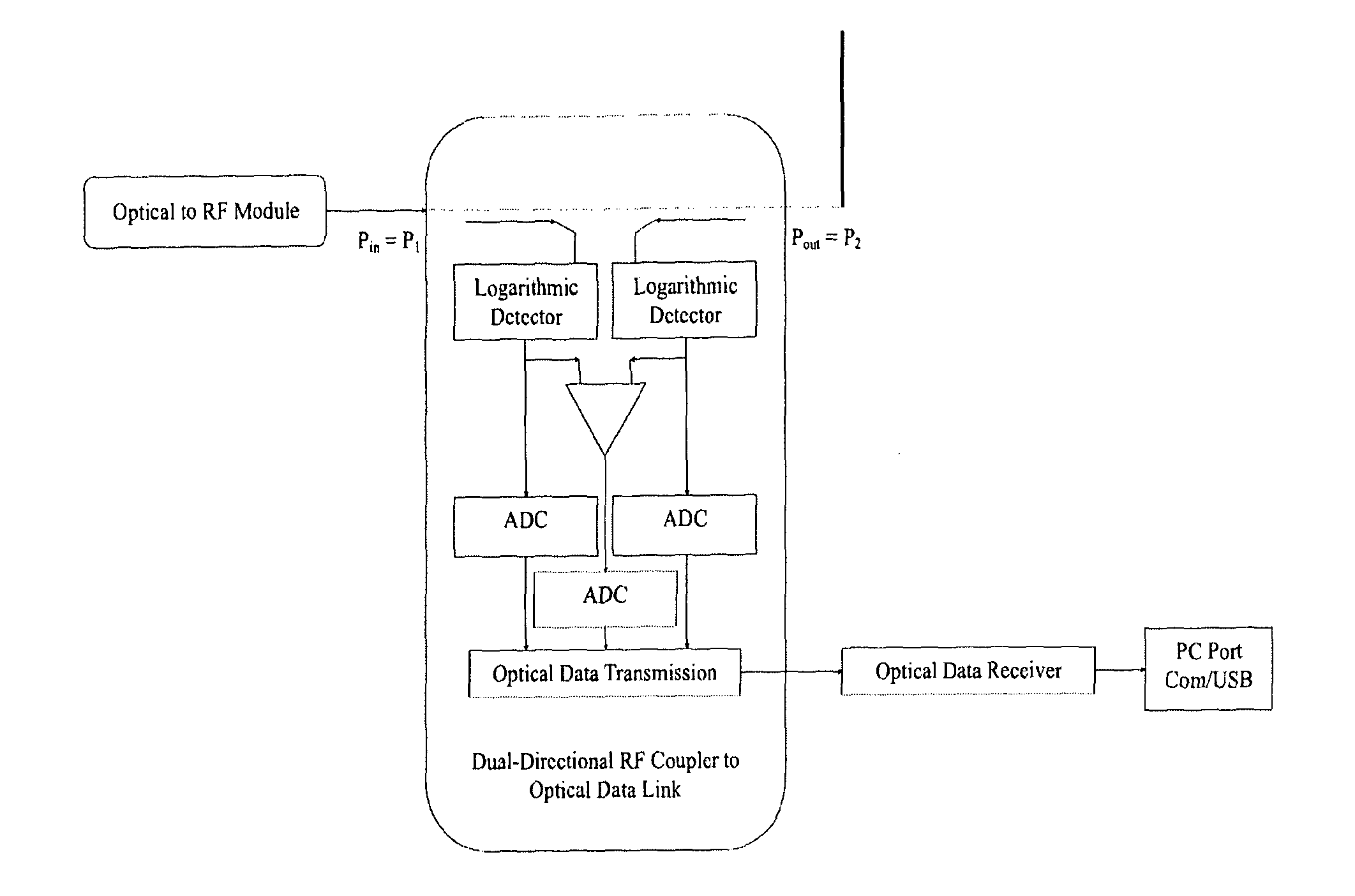
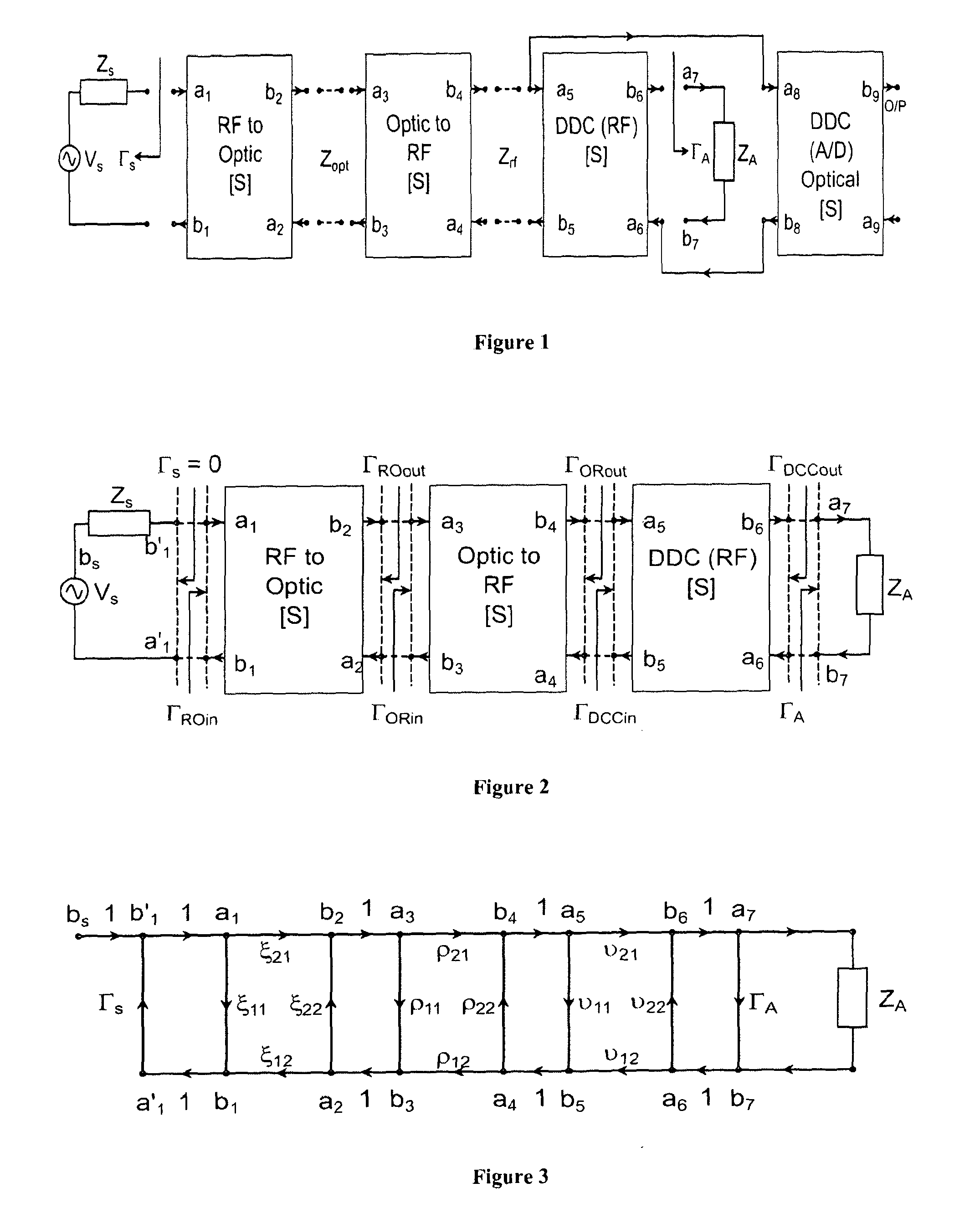
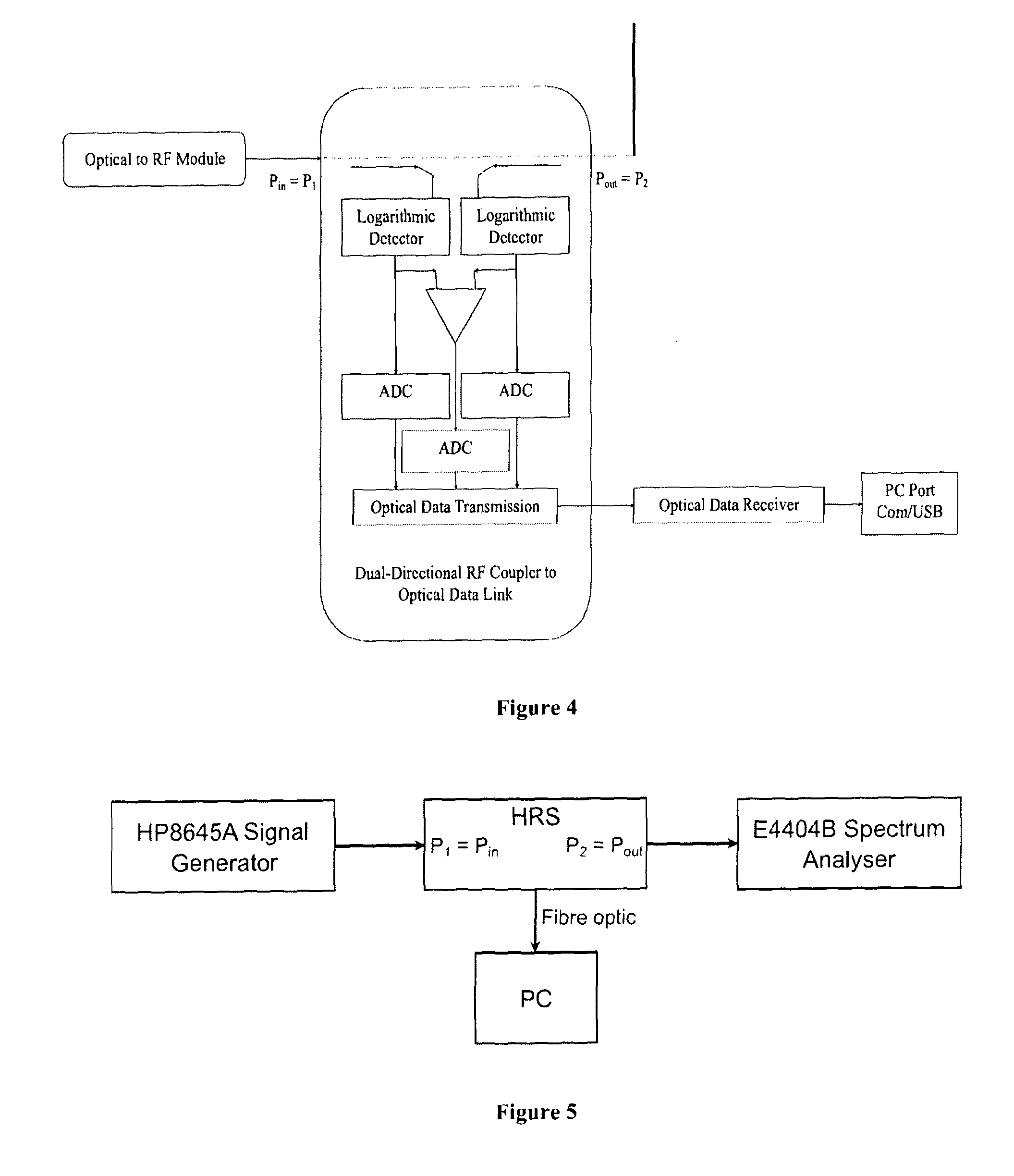
[0053]FIG. 1 shows the signal flow network analysis of the HRS which can be used to reduce complicated networks to relatively simple input-output relations. The RF network may then be characterised using scattering parameters. This technique is used to analyse the HRS and obtain the system's scattering parameters. For the network analysis the HRS consists of four modules; each module is a two-port network represented by a block which has two input ports and two output ports. The ports associated with each module are:

The RF to Optical Module

[0054]a1 Input incident signal node[0055]a2 Output reflected signal node[0056]b1 Input reflected signal node[0057]b2 Output incident signal node

The Optical to RF Module

[0058]a3 Input incident signal node[0059]a4 Output reflected signal node[0060]b3 Input reflected signal node[0061]b4 Output incident signal node

The Dual-Directional Coupler RF (DDC (RF)) Module

[0062]a5 Input incident signal node[0063]a6 Output reflected signal node[0064]b5 Input ref...


PUM


Abstract

A RF signal test and measurement system capable of measuring forward and reverse signal parameters of RF components including Electrically Small Antennas (ESA) and capable of being integrated within a communications system to aid the automatic retuning of antennas.

Description

TECHNICAL FIELD OF THE INVENTION[0001]This invention relates to a Radio Frequency (RF) signal test and measurement system capable of measuring forward and reverse signal parameters of RF components including antennas and particularly including Electrically Small Antennas (ESA) and more particularly relates to a RF test and measurement system capable of being integrated within a communications system to aid the automatic retuning of antennas.BACKGROUND TO THE INVENTION[0002]It is necessary when developing RF equipment to test the RF components such as antennas to verify their actual performance either independently or within an integrated system. Measuring antenna performance is often achieved by connecting an antenna to a reflectometer. This allows a person to measure the Scattering parameter (S-parameter) magnitudes of the antenna using a network analyser, but calibration to allow for unpredictable losses from radiating devices is problematic. This is especially problematic for ESA...

Claims


Application Information

Patent Timeline
IPC IPC(8): G01R29/08
CPCH04B17/20H04B17/103H04B17/14G01R27/06G01R29/0871G01R29/10G01R31/2822H04B17/00G01R23/02
Inventor CLOW, NATHANPERKINS, STEPHEN JOHNMORROW, IVOR LESLIE
Owner THE SEC OF STATE FOR DEFENCE IN HER BRITANNIC MAJESTYS GOVERNMENT OF THE UK OF GREAT BRITAIN & NORTHERN IRELAND
Why Eureka
Try Eureka