Insufflation needle with dual indicator and method of use

a technology of insufflation needle and indicator, which is applied in the field of surgical instruments, can solve the problems of difficult ascertainability, unreliable technique, and fatal consequences for users, and achieve the effect of preventing punctures and lacerations of abdominal cavities and minimizing internal organ injury

Active Publication Date: 2012-08-16
KVI LLC
View PDF4 Cites 19 Cited by
  • Summary
  • Abstract
  • Description
  • Claims
  • Application Information

AI Technical Summary

Benefits of technology

[0027]It is yet another aspect of the invention to provide indication means to determine both that the blunt tip of the needle has been expressed or moved forward, past the hollow sharpened outer needle, and has been retracted to expose the sharpened outer needle. It is a further object to provide a device to supply a signal when a sharp point of a surgical instrument successfully penetrates an anatomical cavity. Yet another aspect of the invention is to provide a Veress needle assembly with a dual visual indicator that the pointed end of the needle is either against the abdomen outer wall, preparatory to penetrating the abdominal wall, or that thereafter the point of the needle is against some interior body member within the abdominal cavity, thereby minimizing injury to internal organs. Further, the handle may contain a lens-magnified color indicator, to indicate the location of the blunt tipped needle. This feature comprises two colored bands. The two colored bands are integrated in a single visual indicator. The color bands may be magnified by a lens. One of the colored bands indicates that the blunt end of the inner needle is moved forward and extends beyond the sharp tip of the outer needle. The opposite colored band indicates that the blunt end of the inner needle has not yet been moved forward. This visual signal helps prevent punctures and lacerations of the abdominal cavity by the sharpened tip of the outer needle.

Problems solved by technology

If the needle goes beyond the peritoneum, the needle may perforate the stomach, small bowel, colon, bladder, or major vascular structures, the consequences of which can be fatal.
However, this technique is often unreliable.
It is sometimes difficult for a user, physician or surgeon to ascertain when the internal cavity wall has been breached by the Veress needle or trocar.
Therefore, as is true with the Veress needle, placement of the trocar is also vital, and the reliance of the surgeon on mere tactile senses for proper placement can be fatal.

Method used


Image

  • Insufflation needle with dual indicator and method of use
  • Insufflation needle with dual indicator and method of use
  • Insufflation needle with dual indicator and method of use

Examples


Embodiment Construction

[0044]For the purposes of promoting an understanding of the principles of the invention, reference will now be made to a number of illustrative embodiments illustrated in the drawing and specific language will be used to describe the same.

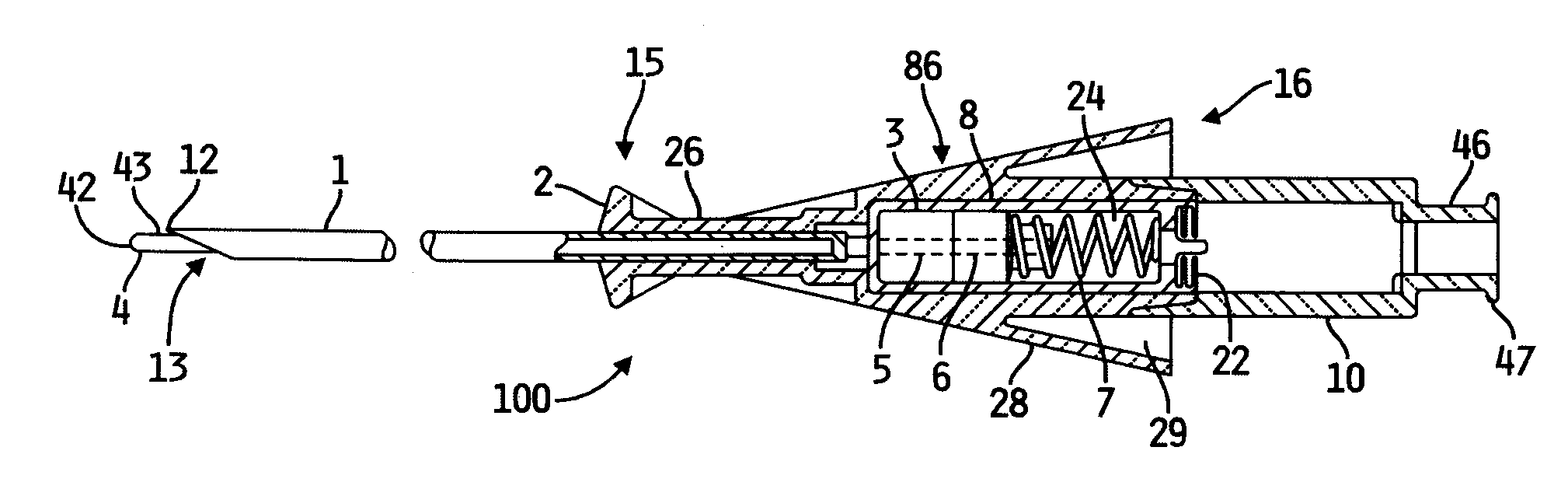
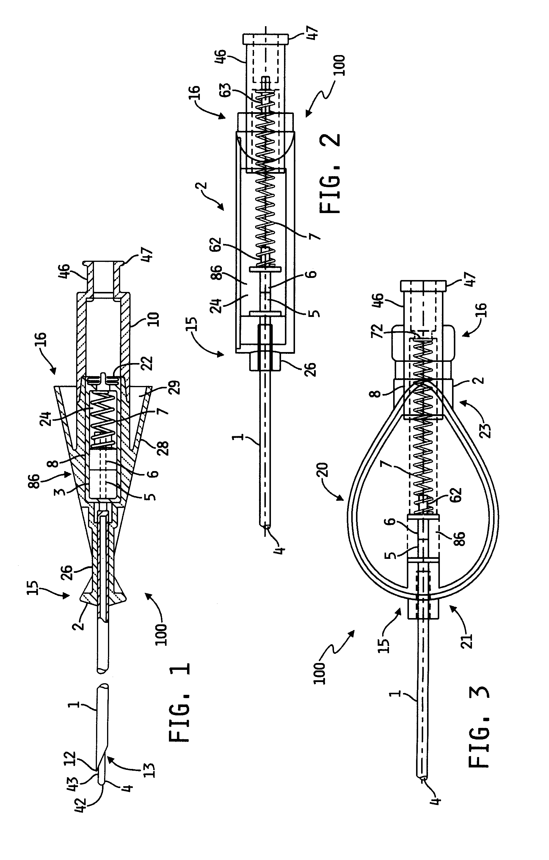
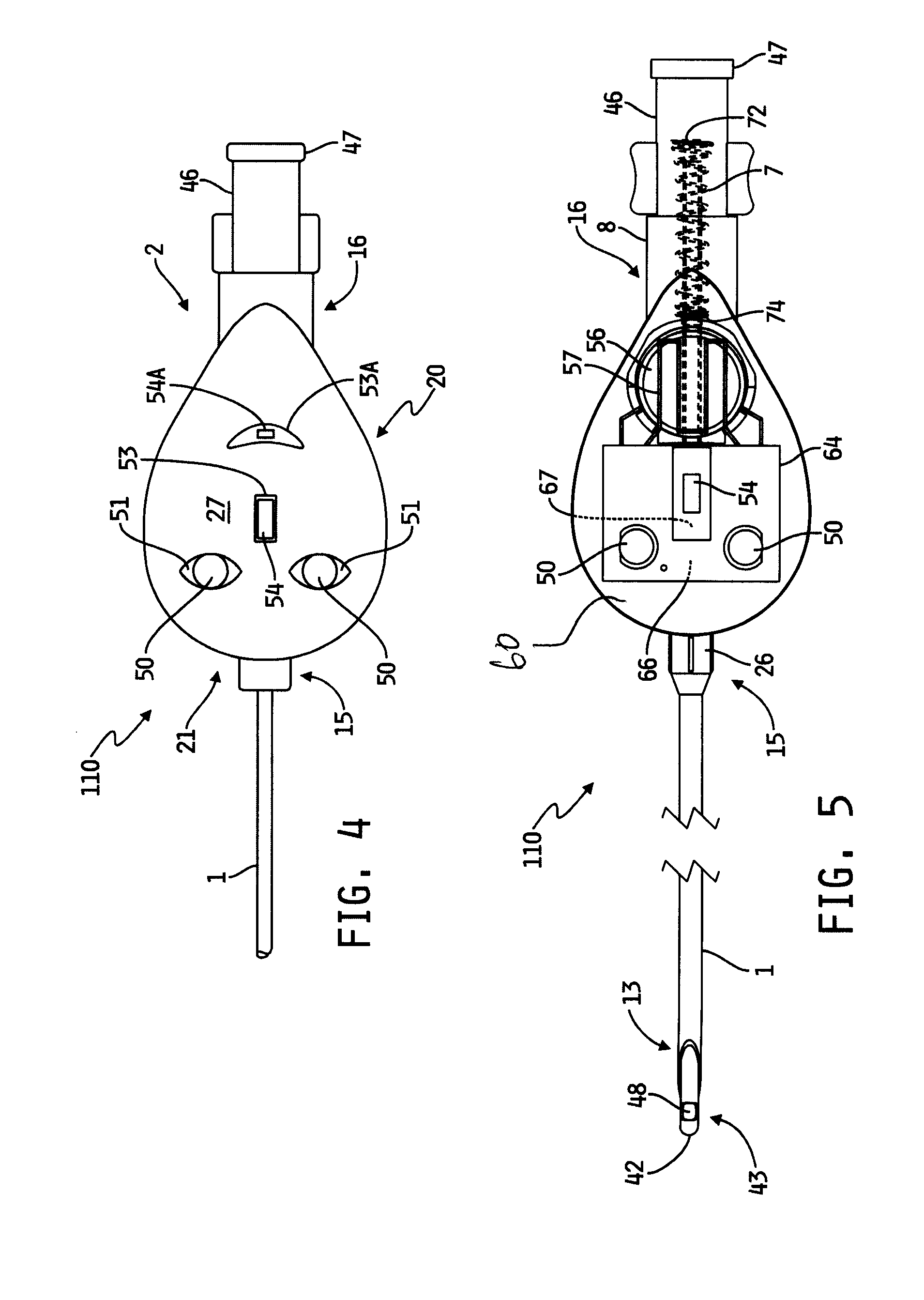
[0045]Referring to FIG. 1 an illustrative embodiment of a medical apparatus, for example a needle 100 is provided. FIG. 1 shows a longitudinal cross-sectional view of one embodiment of the body of an illustrative needle, for example an insufflation-type needle 100. Illustratively, the instrument 100 is used to puncture an anatomical organ structure such as for example and without limitation a cavity wall and providing a passageway via the puncture wound for communicating with the interior of the cavity. The illustrative needle 100 generally comprises a hollow outer needle 1 having a relatively sharpened or sharp tip 12 at its distal end 13. The illustrative outer needle 1 may also be referred to as a hollow needle, or a hollow tube, or an outer tub...


PUM


Abstract

A medical apparatus which comprises a sharpened outer needle and a blunt inner needle slidingly disposed within the outer needle is provided. The apparatus also contains a position indicator to indicate the position of the inner needle within the outer needle, so that the user knows whether the inner needle is in a protective or a non-protective position. The position indicator may be a mechanical visual indicator, an electronic visual indicator, a tactile indicator, an audible indicator or any combination of the above.

Description

[0001]This application claims priority to and the benefit of U.S. Provisional Patent Application No. 61 / 441,934, filed 11 Feb. 2011, the disclosure of which is now incorporated by reference herein.FIELD OF THE INVENTION[0002]This invention relates generally to medical instruments. More particularly, the invention relates generally to an apparatus and method for safely puncturing body tissue, and more specifically to a surgical instrument having at least a single position indicator to positively indicate both when the puncturing portion is in a protective position and when it is in a non-protective position.BACKGROUND OF THE INVENTION[0003]In various medical procedures, one or more surgical instruments may be used to puncture or penetrate body tissue. The body tissue may be penetrated in order to insert the instrument into a body cavity such as for example the abdominal cavity. Throughout the present application, the terms penetrating, piercing and puncturing and formatives thereof a...

Claims


Application Information

Patent Timeline
Patent Type & Authority Applications(United States)
IPC IPC(8): A61B17/34A61M13/00
CPCA61M13/003A61B17/3474A61B2019/4857A61B2017/00115A61B17/3496A61B2090/0811
Inventor WEBER, DAVID P.CLEMENT, THOMAS P.
Owner KVI LLC
Why Eureka
Try Eureka