
Pressure adjustment device of a chambered doctor blade system

Inactive Publication Date: 2012-08-23
KOENIG & BAUER AG
View PDF7 Cites 11 Cited by
  • Summary
  • Abstract
  • Description
  • Claims
  • Application Information

AI Technical Summary

Benefits of technology

[0021]The advantages to be achieved by the invention consist particularly in that by reliably adjusting the pressure inside the chambered doctor blade, both unduly high and unduly low pressures inside the chambered doctor blade and the lines connected thereto are prevented. This is carried out during various phases or operating states of the corresponding printing press, wherein it is ensured that appropriate pressure conditions are maintained in the case of both high viscosity and low viscosity ink. A transfer of ink to the screen roller is thereby optimized, and pressure-induced damage and / or reductions in quality are prevented or at least substantially diminished. More particularly, by establishing a pressure that lies within a specific range, the service life of doctor blades being used can also be increased substantially, since frictional forces between doctor blade and roller and between doctor blade and viscous ink are influenced by the level of pressure inside the chambered doctor blade.
[0029]By applying the coating exclusively to the side of a doctor blade that faces the ink, said doctor blade forming an acute angle with the trailing portion of a tangent plane on an adjoining roller, in the direction of rotation of said roller, through the line of contact between roller and doctor blade, the advantage results that the surface of the coating requires no additional precision processing during its application, since this surface is no longer in contact solely with the screen roller and therefore is not responsible for a uniform application of ink.

Problems solved by technology

This results in a savings in terms of effort and cost, and makes active, potentially vulnerable control and / or regulating units unnecessary.

Method used


Image

  • Pressure adjustment device of a chambered doctor blade system
  • Pressure adjustment device of a chambered doctor blade system
  • Pressure adjustment device of a chambered doctor blade system

Examples


Embodiment Construction

[0041]What is stated above and in the following relates to ink. It should be pointed out, however, that a varnish, for example, or generally some other medium that can be conveyed by means of a pump and / or that has thixotropic properties can be handled using a pressure adjustment device as described. Therefore, all statements are to be understood to mean that printing ink or generally ink also refers to varnish or similar media. It should further be pointed out that what is stated above and in the following refers to pressing, wherein this generally refers to an overpressure relative to a prevailing atmospheric pressure.

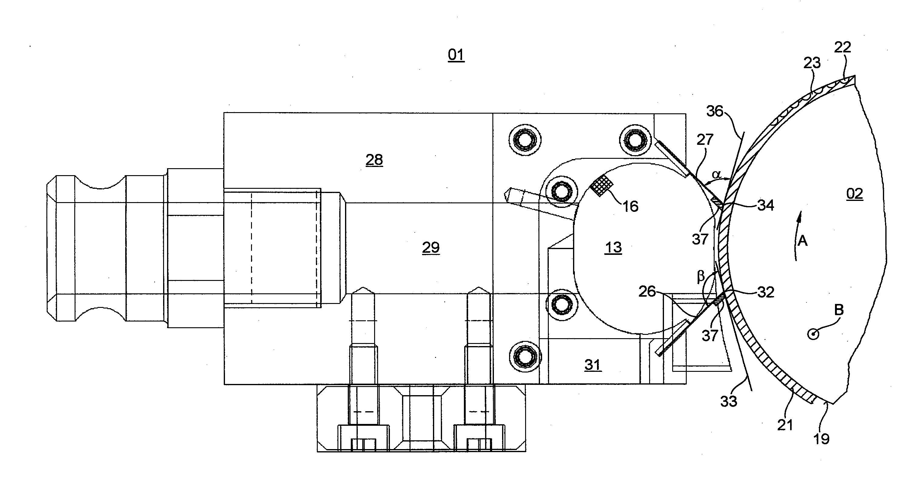
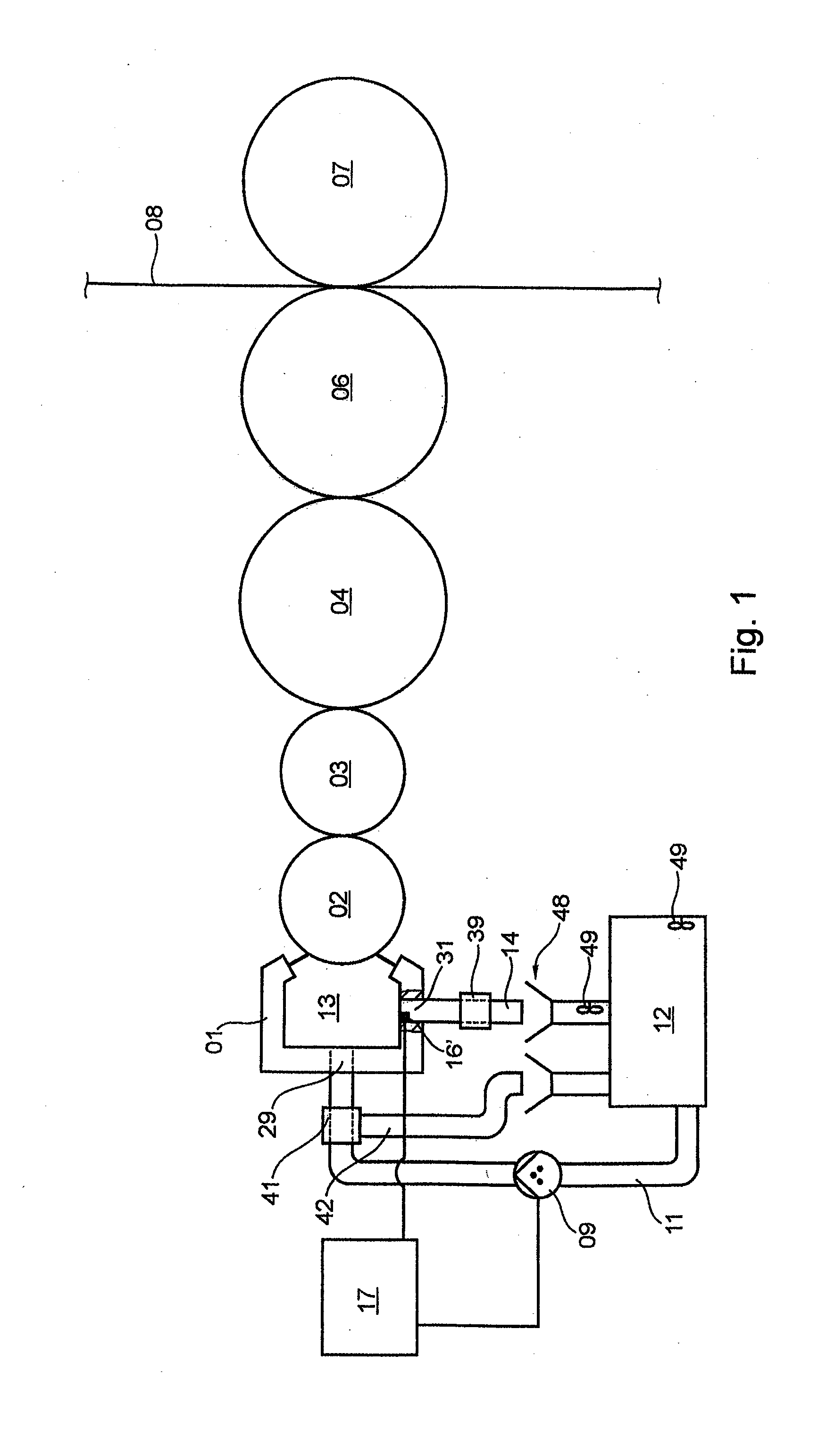
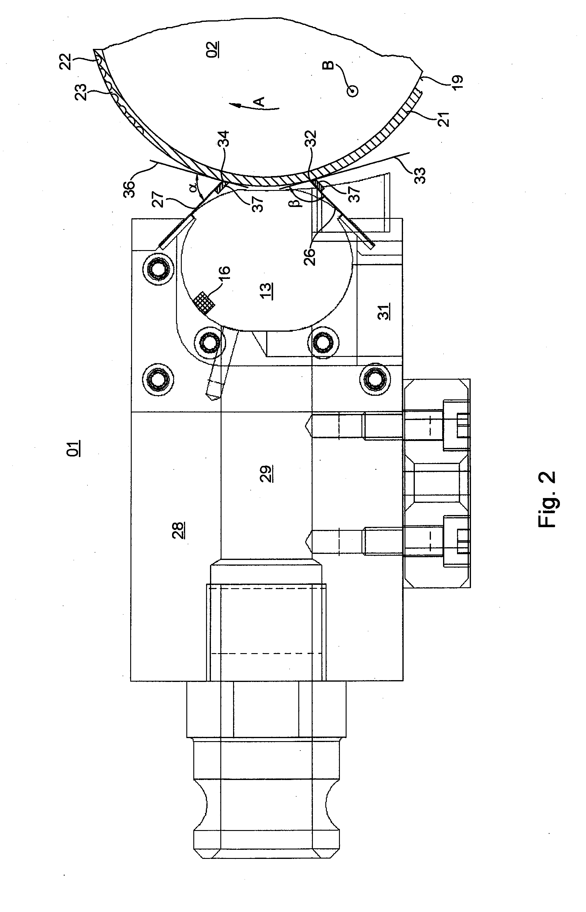
[0042]FIG. 1 shows a printing couple of a printing press, particularly of an offset printing press, by way of example, in which a chambered doctor blade 01 can be used. The printing couple shown can be used, for example, for waterless sheet-fed or web-fed offset printing, and has at least one chambered doctor blade 01, which is used to apply ink to an adjoining rolle...


PUM


Abstract

A pressure adjustment device of a chambered doctor blade system of a printing press includes at least one chambered doctor blade, at least one ink chamber having at least one supply line connected to an ink reservoir and having at least one drain line or overflow opening that at least partially forms a return flow path of the medium from the at least one ink chamber to the at least one ink reservoir. At least one pressure release valve is arranged in the one of the drain line or overflow opening. Another pressure release valve is also arranged in the at least one supply line. One of the pressure release valves is configured as a passive pressure release valve. The at least one pressure release valve arranged in the at least one supply line has a line connection to at least one bypass line. That bypass line is arranged to at least partially form a return flow path of the medium from the supply line to the ink reservoir.

Description

CROSS-REFERENCE TO RELATED APPLICATIONS[0001]This application is the U.S. national phase, under 35 USC 371 of PCT / EP2010 / 064521, filed Sep. 30, 2010; published as WO 2011 / 051 072 A1 on May 5, 2011 and claiming priority to DE 10 2009 046 078.0, filed Oct. 28, 2009, the disclosures of which are expressly incorporated herein by reference.FIELD OF THE INVENTION[0002]The invention relates to a pressure adjustment device of a chambered doctor blade system of a printing press. The chambered doctor blade system has at least one chambered doctor blade and at least one ink chamber that has at least one supply line which is connected to at least one ink reservoir. The at least one ink chamber also has at least one drain line and / or outflow opening which at least partially forms a return flow path for a medium from the at least one ink chamber to the at least one ink reservoir. At least one pressure relief valve is arranged in the at least one drain line and / or outflow opening. At least one pre...

Claims


Application Information

Patent Timeline
IPC IPC(8): B41F31/04
CPCB41F31/08B41F31/027
Inventor MASUCH, BERND KURTREDER, WOLFGANG OTTO
Owner KOENIG & BAUER AG
Learn More