Device for variably adjusting the control times of gas exchange valves of an internal combustion engine

a technology of gas exchange valve and control time, which is applied in the direction of machines/engines, mechanical equipment, engine components, etc., can solve problems such as the inability to adjust the speed or accuracy, and achieve the effect of simplifying installation

Inactive Publication Date: 2012-08-23
SCHAEFFLER TECH AG & CO KG
View PDF5 Cites 9 Cited by
  • Summary
  • Abstract
  • Description
  • Claims
  • Application Information

AI Technical Summary

Benefits of technology

[0027]The above-described adjustment concept demands a defined angular position of the inner sleeve and outer sleeve relative to the camshaft, because the interaction must be synchronized with the camshaft torques occurring at fixed angular positions. This defined rotational position is now attained by means of a simplification of installation such that the inner and outer sleeve are fixed in the correct position relative to one another, and then the entire control valve is attached to the camshaft, which has likewise previously been rotated into a defined angular position. During the attachment, a positive locking action between the inner sleeve and outer sleeve is released by means of an axial displacement, such that the relative rotation between the inner sleeve and outer sleeve is made possible. This is advantageously achieved by virtue of the magnet which is used for adjusting the valve piston being flange-mounted centrally in front of the camshaft, and in so doing displacing the inner sleeve. It is furthermore possible here for a rotation prevention means, for example a pin or a lug on the inner sleeve, to engage into a corresponding cutout in the magnet, wherein said engagement advantageously takes place first, and then the magnet is fastened and in so doing, via the rotation prevention means, displaces the inner sleeve.

Problems solved by technology

In the case of a single-piece design of the valve housing and therefore a relative rotation of the valve piston, which is fixed against rotation, and of the rotatable valve housing, it is possible under some circumstances for jamming, or an impairment of the adjustment speed or accuracy, to occur during the axial adjustment of the valve piston.
This possible disadvantage is now counteracted in that the valve housing is of two-piece design, with an inner sleeve which is fixed against rotation and with a rotatable outer sleeve.

Method used


Image

  • Device for variably adjusting the control times of gas exchange valves of an internal combustion engine
  • Device for variably adjusting the control times of gas exchange valves of an internal combustion engine
  • Device for variably adjusting the control times of gas exchange valves of an internal combustion engine

Examples


Embodiment Construction

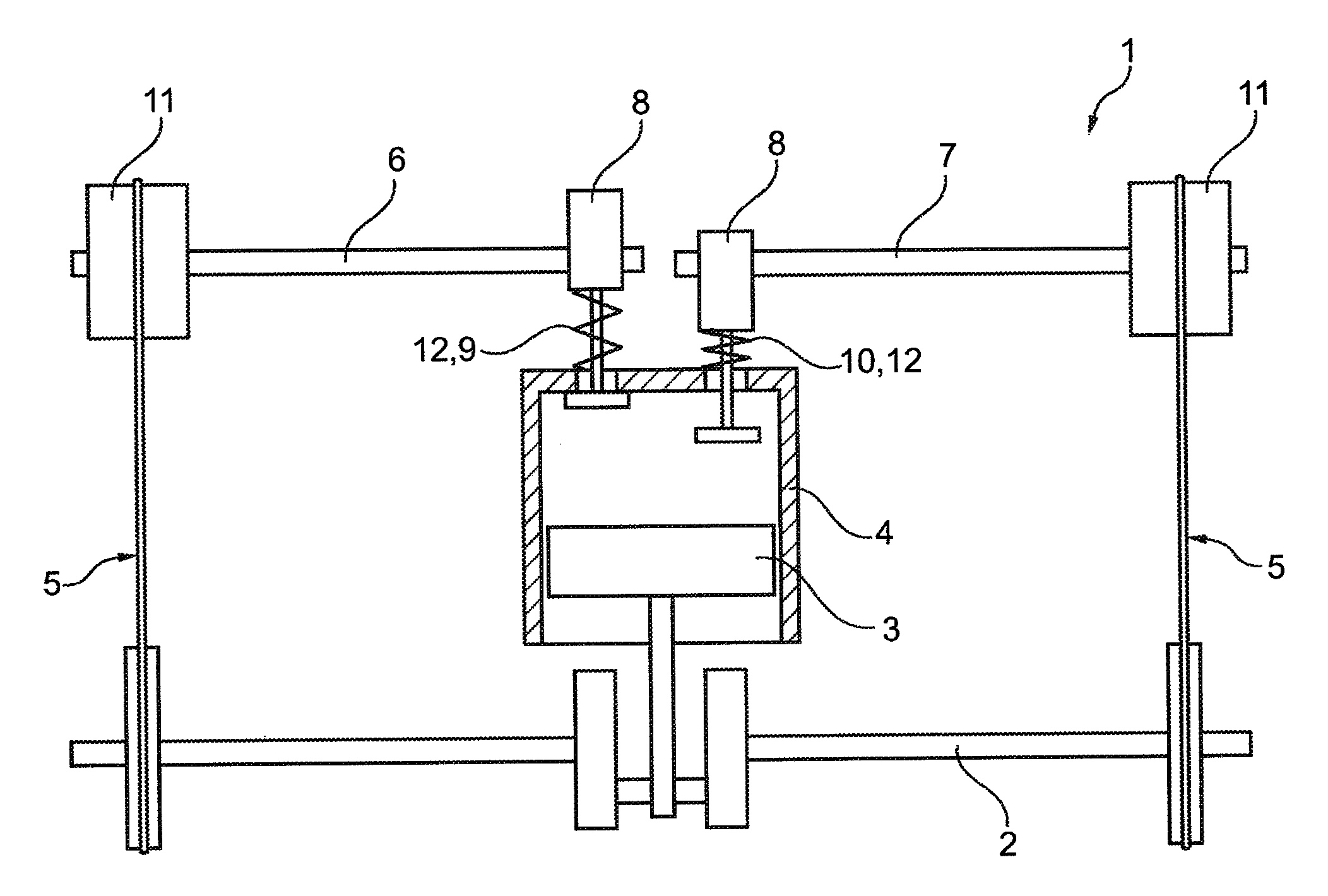
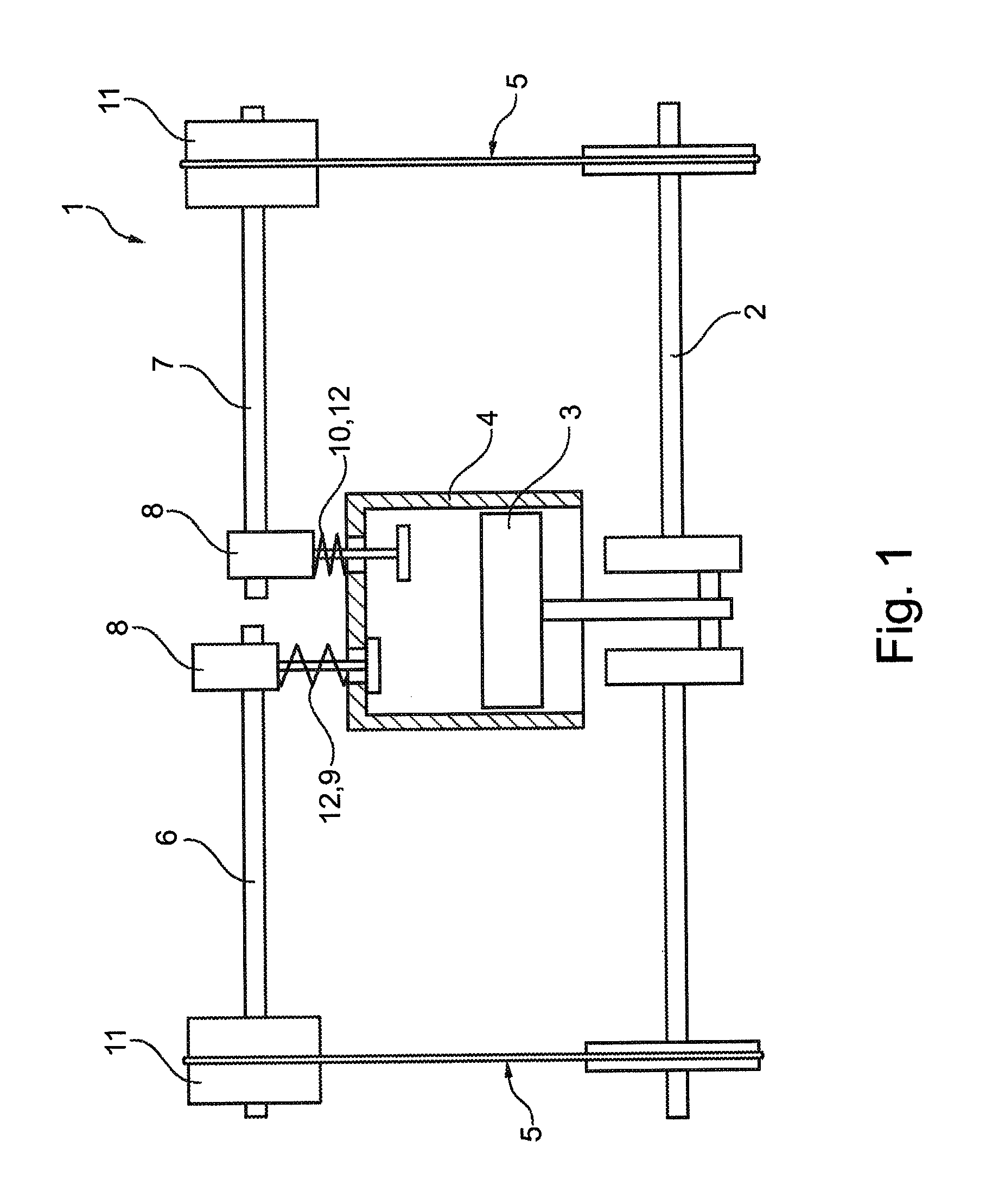
[0044]FIG. 1 illustrates an internal combustion engine 1, with a piston 3 which is connected to a crankshaft 2 being indicated in a cylinder 4. In the illustrated embodiment, the crankshaft 2 is connected via in each case one traction mechanism drive 5 to an intake camshaft 6 and an exhaust camshaft 7, wherein a first and a second camshaft adjuster 11 for variably adjusting the timing of gas exchange valves 9, 10 of an internal combustion engine can effect a relative rotation between the crankshaft 2 and the camshafts 6, 7. Cams 8 of the camshafts 6, 7 actuate one or more intake gas exchange valves 9 or one or more exhaust gas exchange valves 10. The intake gas exchange valves 9 and the exhaust gas exchange valves 10 will hereinafter be referred to for short as cylinder valves 12. It may likewise be provided that only one of the camshafts 6, 7 is equipped with a device 11, or only one camshaft 6, 7 is provided, which is equipped with a camshaft adjuster 11. The intake camshaft 6 and...


PUM


Abstract

A camshaft adjuster for actuating cylinder valves of a combustion engine, retardation torques are imparted back to the adjuster by the camshaft when cams are running on, and advance torques are imparted back to the adjuster by the camshaft when cams are running off, supply and removal of pressure medium is controllable by a control unit, a torque mode or pump mode is selectively adjusted by the control unit, and primarily camshaft torque is used in torque mode to build pressure in the first or second partial chamber, whereas pressure build-up in the first or second partial chamber primarily occurs in the pump mode via the pump. The control unit includes a control valve with inner and outer sleeves, and an adjustment direction and the pump or torque mode is adjustable by the control valve by the relative rotational position of the inner sleeve to the outer sleeve.

Description

CROSS-REFERENCE TO RELATED APPLICATIONS[0001]This application is a continuation of PCT / EP2010 / 067168, filed Nov. 10, 2010, which claims the benefit of German Patent Application No. 10 2009 056 020.3, which are incorporated herein by reference as if fully set forth.FIELD OF THE INVENTION[0002]The invention relates to a device for variably adjusting the timing of gas exchange valves of an internal combustion engine, having a hydraulic phase adjustment unit, wherein the phase adjustment unit can be placed in drive connection with a crankshaft and with a camshaft and has at least one advance chamber and at least one retardation chamber, to and from which pressure medium can be supplied and discharged via pressure medium lines, wherein a phase position of the camshaft relative to the crankshaft can be adjusted by means of a supply of pressure medium to the adjustment chambers.BACKGROUND OF THE INVENTION[0003]In modern internal combustion engines, devices for variably adjusting the timing...

Claims


Application Information

Patent Timeline
Patent Type & Authority Applications(United States)
IPC IPC(8): F01L1/344
CPCF01L1/34409F01L1/3442
Inventor SCHEIDIG, GERHARD
Owner SCHAEFFLER TECH AG & CO KG
Why Eureka
Try Eureka