Magneto-resistive effect element having spacer layer including gallium oxide layer with metal element

Active Publication Date: 2012-08-23
TDK CORPARATION
View PDF5 Cites 4 Cited by
  • Summary
  • Abstract
  • Description
  • Claims
  • Application Information

AI Technical Summary

Benefits of technology

[0010]A magneto-resistive effect (MR) element of the present invention includes: first and second magnetic layers in which a relative angle formed by magnetization directions changes according to an external magnetic field; and a spacer layer positioned betw

Problems solved by technology

On the other hand, even when gallium oxide is used for the spacer layer, a problem of

Method used


Image

  • Magneto-resistive effect element having spacer layer including gallium oxide layer with metal element
  • Magneto-resistive effect element having spacer layer including gallium oxide layer with metal element
  • Magneto-resistive effect element having spacer layer including gallium oxide layer with metal element

Examples


first embodiment

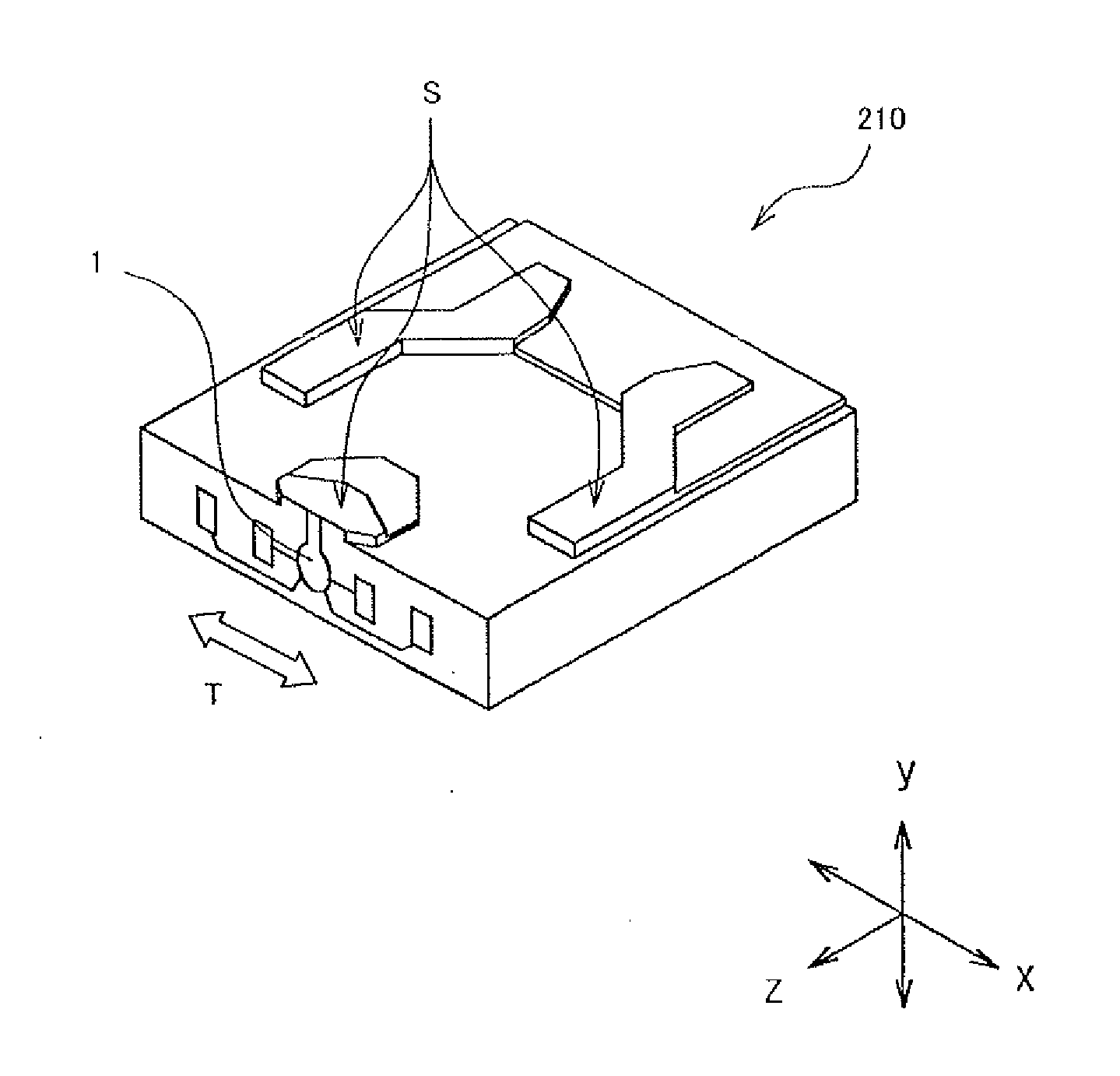
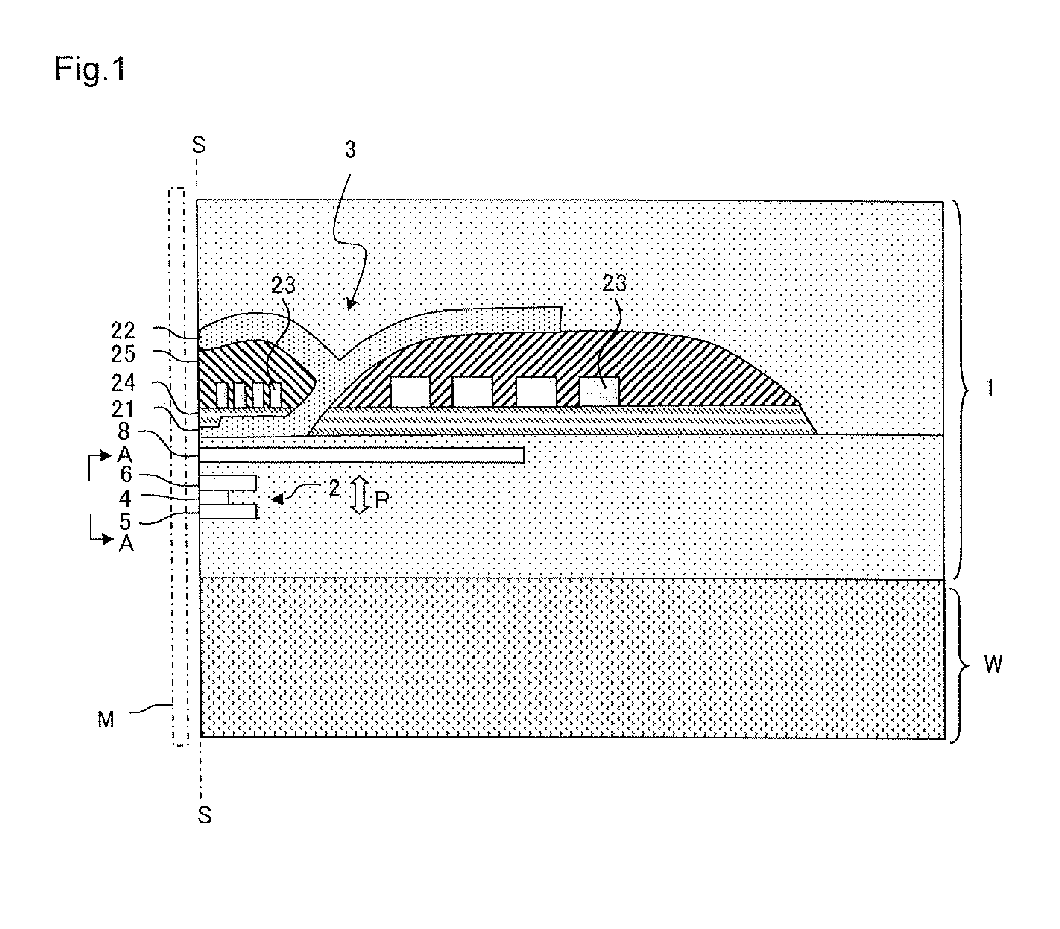
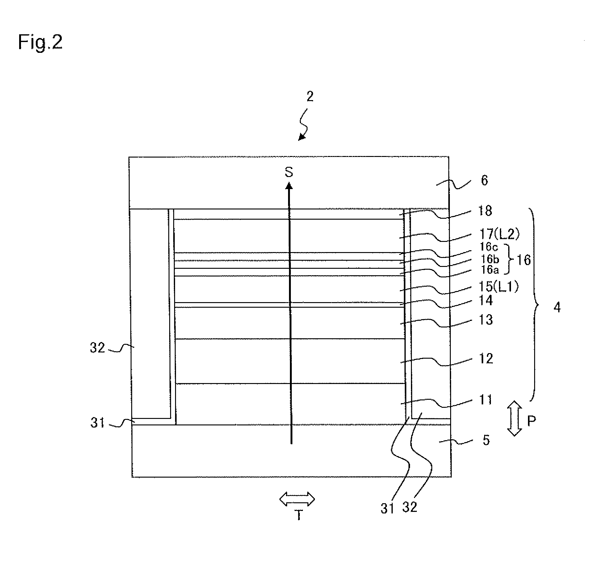
[0025]FIG. 1 illustrates a main part cross sectional view of a thin film magnetic head 1 according to a first embodiment. The thin film magnetic head 1 is formed above a substrate W and includes a reproducing head 2 and a recording head 3. FIG. 2 is a side view of the reproducing head 2, as viewed from the A-A direction of FIG. 1, and illustrates a layer configuration of the reproducing head 2 on an air bearing surface S. The air bearing surface S is a surface of the thin film magnetic head 1 that faces a recording medium M. First, a description will be given regarding a configuration of the reproducing head 2 with reference to FIG. 2.

[0026]The reproducing head 2 includes a spin valve type MR element 4, upper and lower shield layers 6 and 5 disposed so as to sandwich the MR element 4 in a film surface orthogonal direction (lamination direction) P, and bias magnetic field application layers 32 disposed on both sides in a track width direction T of the MR element 4 (sheet surface orth...

second embodiment

[0043]A thin film magnetic head 1 of the present embodiment is the same as the first embodiment indicated in FIG. 1 with the exception of the configuration of the reproducing head 2. FIG. 3 and Table 2 illustrate a layer configuration of such an MR element. A reproducing head 102 includes an MR element 104 in which a large number of layers are laminated in the same manner as the first embodiment, and upper and lower shield layers 106 and 105 that are disposed so as to sandwich the MR element 104 in the film surface orthogonal direction P (lamination direction). The upper and lower shield layers 106 and 105 are also used as electrodes for a sense current S to cause the sense current S to flow in the film surface orthogonal direction P of the MR element 104.

[0044]With the present embodiment, a first magnetic layer L1 and a second magnetic layer L2 are magnetization free layers 115 and 117 in both of which the magnetization direction changes according to the external magnetic field. A ...

first example

[0053]A multilayer film with the layer configuration illustrated in Table 1 was formed above a substrate W composed of Al2O3—TiC (ALTIC) by using a radio frequency (RF) sputtering device. Mg, Zn, In or Al was used as a metal element to add to a main spacer layer. In the present example, these elements were added as oxides. In the following explanation, oxides of Mg, Zn, In and Al are collectively referred to as MOx. The film thickness of the main spacer layer was 0.9 nm. The main spacer layer was formed by disposing a target composed of Ga2O3 and a target composed of MOx in a reaction chamber and colliding argon gas simultaneously with these targets. A target composed of Ga2O3 to which MOx was added may be used. Copper was used for the first nonmagnetic layer 16a and zinc was used for the second nonmagnetic layer 16c. After the film formation, heat treatment was performed at 250° C. for three hours. A plane size (junction size) of the MR element was 0.2 μm×0.2 μm.

[0054]In the above-...


PUM


Abstract

A magneto-resistive effect (MR) element includes: first and second magnetic layers in which a relative angle formed by magnetization directions changes according to an external magnetic field; and a spacer layer positioned between the first magnetic layer and the second magnetic layer. The spacer layer includes a main spacer layer composed of gallium oxide as a primary component and containing at least one metal element selected from a group of magnesium, zinc, indium and aluminum.

Description

BACKGROUND OF THE INVENTION[0001]1. Field of the Invention[0002]The present invention relates to a magneto-resistive effect (MR) element and particularly to a configuration of a spacer layer.[0003]2. Description of the Related Art[0004]Reproducing heads with high sensitivity and high output are in demand in conjunction with condensing of high recording density in hard disk drives (HDD). As an example of this type of reproducing head, a spin valve head has been developed. A spin valve head includes a nonmagnetic metal layer and a pair of ferromagnetic layers positioned on both sides of the nonmagnetic metal layer in a manner of contacting the nonmagnetic metal layer. The magnetization direction of one side of the ferromagnetic layers is pinned in one direction (hereinafter, this type of layer is referred to as a magnetization pinned layer), and the magnetization direction of the other side of the ferromagnetic layers freely rotates in response to an external magnetic field (hereinaft...

Claims


Application Information

Patent Timeline
IPC IPC(8): G11B5/56G11B5/48G11B5/39
CPCB82Y10/00G11B5/3906B82Y25/00G11B2005/3996G11B5/3912Y10T428/1121G11B5/3929
Inventor KOIKE, HAYATOCHOU, TSUTOMUTSUCHIYA, YOSHIHIROMATSUZAWA, HIRONOBU
Owner TDK CORPARATION
Why Eureka
Try Eureka