Iterative reduction of artifacts in computed tomography images using forward projection and an edge-preserving blur filter

a computed tomography and blur filter technology, applied in image enhancement, instruments, applications, etc., can solve the problem that the forward projected values don't match the original projection data exactly, and achieve the effect of reducing noise and beam hardening artifacts, eliminating the risk of misclassification, and improving results

Active Publication Date: 2012-08-23
BOAS FRANZ EDWARD
View PDF10 Cites 24 Cited by
  • Summary
  • Abstract
  • Description
  • Claims
  • Application Information

AI Technical Summary

Benefits of technology

[0012]Several key variations on the basic framework described above can improve the image quality. First, to reduce noise and streaking, an edge-preserving blur filter 4 is applied to the image before forward projection. Second, the forward projected values don't match the original projection data exactly, due to beam hardening, density outside the reconstructed region, and other factors. Therefore, we add a linear function to the forward projected values to eliminate discontinuities when they are spliced back into the experimental projection data. Finally, to further reduce streaking, rays passing near metal are replaced with a weighted average of the experimental projection data and the forward projected data, which allows for a smoother transition.
[0014]The present invention solves these problems with FP-MAR as follows. First, instead of tissue class segmentation, an edge-preserving blur filter is used to reduce noise and beam hardening artifacts before forward projection. This allows for use of the actual Hounsfield units, instead of idealized tissue classes. In addition, the edge-preserving blur filter blurs out streaks through soft tissue, thus eliminating the risk of misclassification. The edge-preserving blur filter incorporates information from neighboring pixels, whereas tissue class segmentation only considers one pixel at a time. Second, we iterate the method to improve the results. Third, we apply an adaptive filter to the experimental projection data to reduce photon counting (Poisson) noise.
[0015]This invention addresses the major sources of artifacts in CT images. Poisson counting error is reduced by expanding the detector elements in regions with low photon counts. Beam hardening effects, edge effects, and patient motion are addressed by deleting the metal. Projection data that involves metal is then replaced with values derived from the rest of the projection data.
[0016]Despite a long history of attempts to reduce metal artifacts in CT, this invention is the first metal artifact reduction technique shown to produce statistically significantly better image quality 8 then other methods for clinical scans (FIG. 3). It avoids introducing new artifacts, which are seen with other methods, such as LI 9 or SART 11. It is also the first metal artifact reduction technique that has been shown to change the imaging diagnosis (FIG. 4).

Problems solved by technology

Second, the forward projected values don't match the original projection data exactly, due to beam hardening, density outside the reconstructed region, and other factors.
Furthermore, a dark streak through soft tissue may cause it to be incorrectly classified as air (which would introduce new artifacts).

Method used


Image

  • Iterative reduction of artifacts in computed tomography images using forward projection and an edge-preserving blur filter
  • Iterative reduction of artifacts in computed tomography images using forward projection and an edge-preserving blur filter
  • Iterative reduction of artifacts in computed tomography images using forward projection and an edge-preserving blur filter

Examples


Embodiment Construction

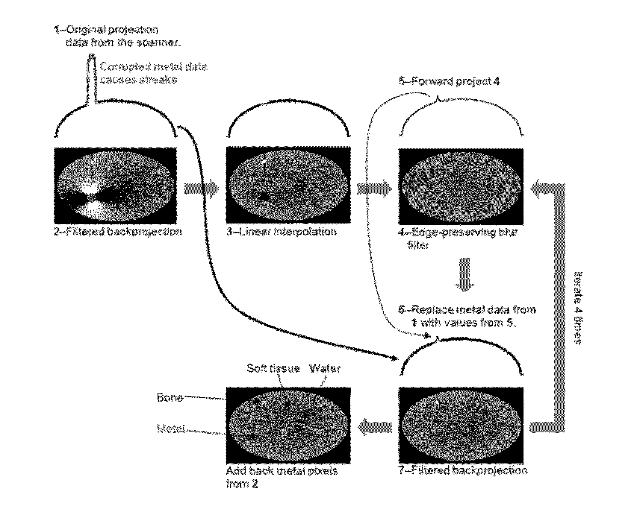
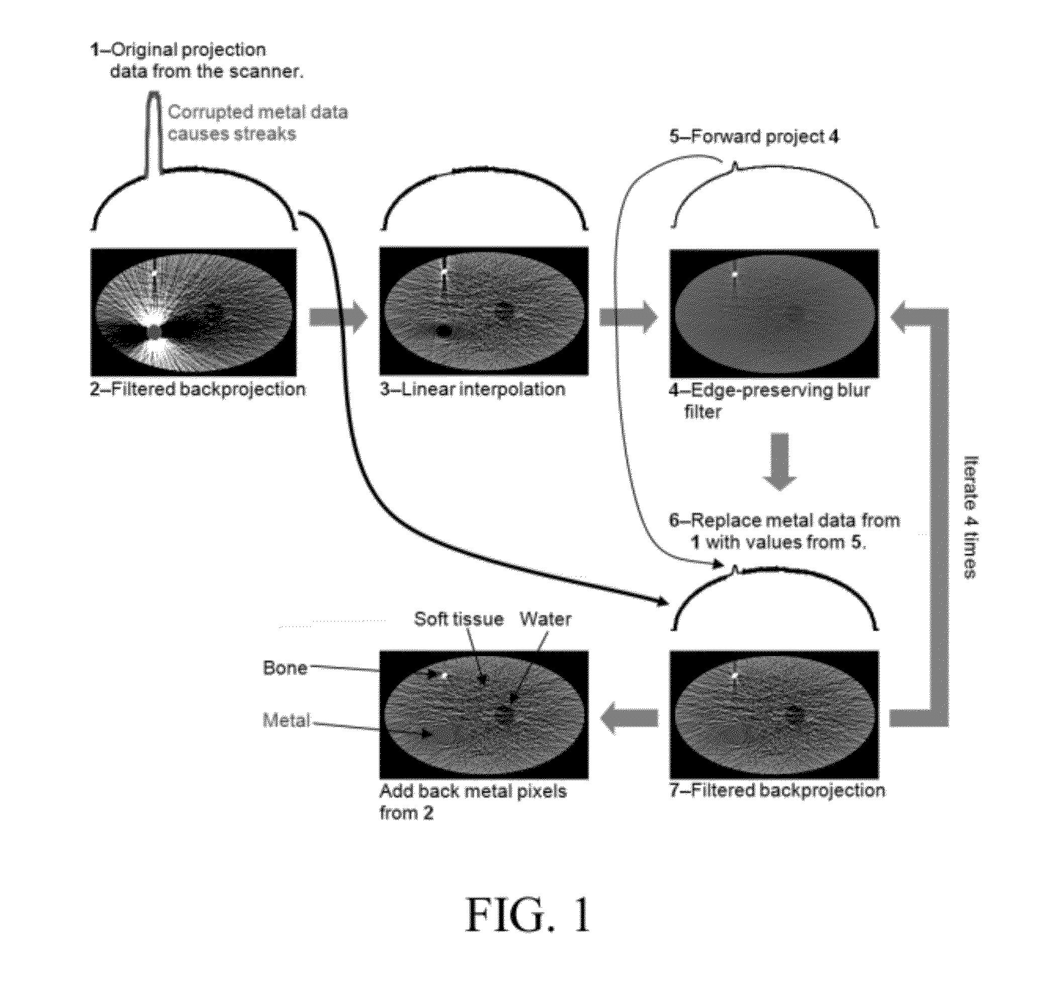
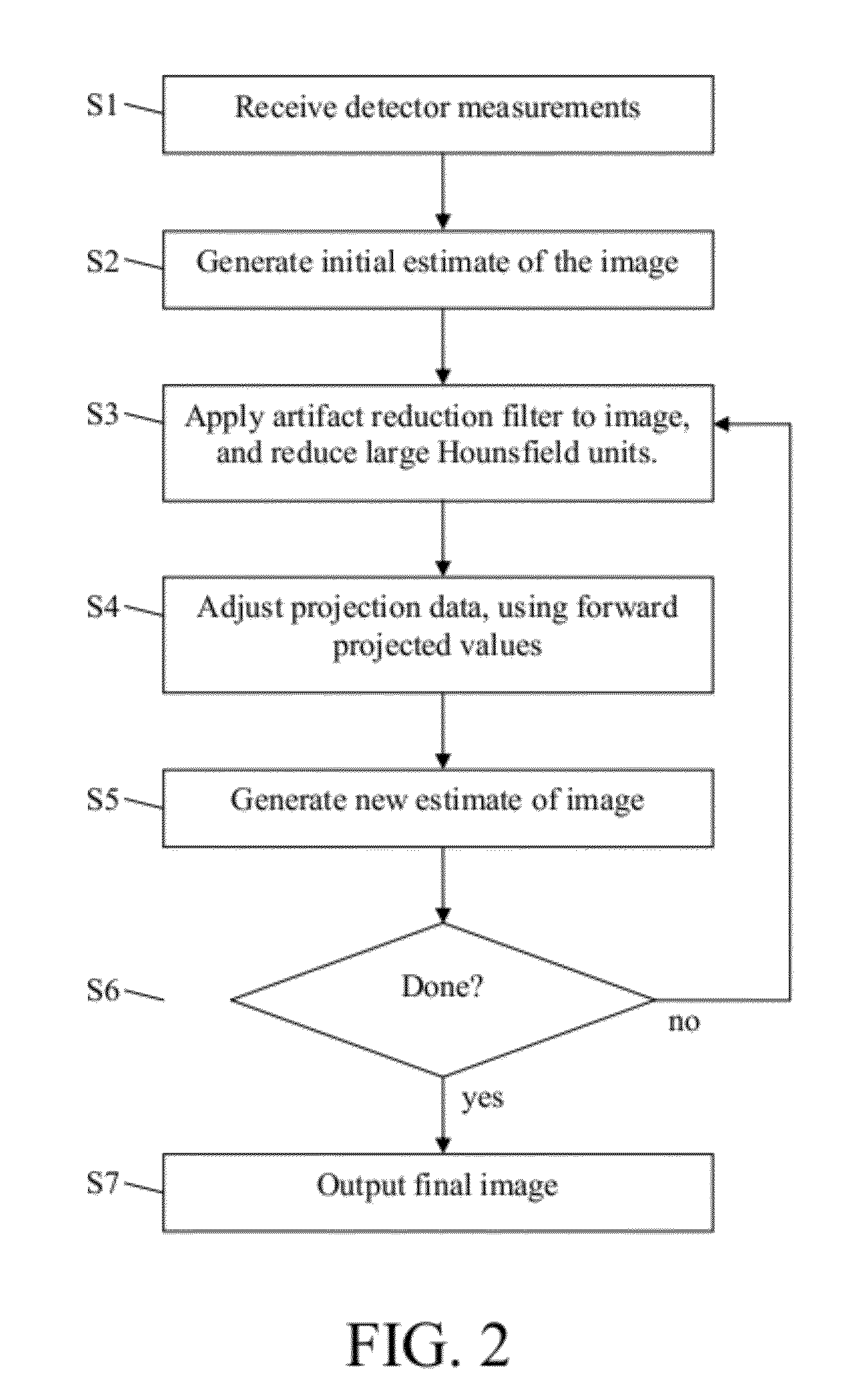
[0021]A flowchart showing one embodiment is illustrated in FIG. 2 and described in detail below.

[0022]Step S1. Projection data are obtained from a plurality of detectors configured to detect transmitted, emitted, or reflected photons, other particles, or other types of radiated energy. These measurements are made by a CT, PET, SPECT, or other type of scanner. If the detector measurements are not available (for example, if the manufacturer of the scanner does not allow access to the detector measurements), then experimental projection data can be estimated by forward projecting reconstructed images produced by the scanner. The streaks largely cancel out during the forward projection procedure, thus resulting in a reasonably accurate estimate of the experimental projection data.

[0023]Step S2. Generate an initial estimate of the image.

[0024]The projection data can be pre-processed to account for beam-hardening, scatter, refraction, diffraction, or other phenomena. Furthermore, low phot...


PUM


Abstract

We present an iterative method for reducing artifacts in computed tomography (CT) images. First, a filter is applied to the experimental projection data that adaptively expands the detector element size in regions with low photon counts, until the desired number of photons are detected. The initial image is then calculated using an existing reconstruction technique. In each iteration, artifacts and noise in the current image are reduced by using an edge-preserving blur filter. Metal pixels (determined from the initial image) are replaced with smaller values. The resulting image is forward projected. Rays that go through metal are replaced with the forward projected values. Rays that do not pass near metal are kept at the experimental values. Filtered backprojection is then performed on the new projection data to determine the updated image. Finally, after the last iteration, metal pixels are copied from the initial image.

Description

REFERENCES CITEDU.S. Patent Documents[0001]5,907,594May 1999Lai378 / 45,933,471August 1999Kalvin378 / 47,023,951 B2April 2006Man378 / 87,636,461 B2December 2009Spies382 / 1282008 / 0273651November 2008Boas378 / 4OTHER PUBLICATIONS[0002]G. Glover, et al, “An algorithm for the reduction of metal clip artifacts in CT reconstructions,”Medical Physics, vol. 8, pp. 799-807, November-December 1981.[0003]W. Kalender, et al, “Reduction of CT artifacts caused by metallic implants,”Radiology, vol. 164, pp. 576-77, August 1987.[0004]A. C. Kak and M. Slaney, Principles of computerized tomographic imaging, IEEE Press, New York, 1988.BACKGROUND OF THE INVENTION[0005]A computed tomography (CT) scanner uses X-rays to determine the three-dimensional structure of an object. X-ray beams (“rays”) are passed through the object from different angles, and “detector elements” (also known as “detectors”) on the other side measure the intensity of each attenuated ray. “Ray” can also refer to the path traversed by X-rays ...

Claims


Application Information

Patent Timeline
Patent Type & Authority Applications(United States)
IPC IPC(8): A61B6/03G06K9/40
CPCA61B6/5205A61B6/5258G06T2207/20192G06T2211/424G06T5/002G06T11/005
Inventor BOAS, FRANZ EDWARD
Owner BOAS FRANZ EDWARD
Why Eureka
Try Eureka