Integrated recirculating fuel cell system

a fuel cell and recirculating technology, applied in the field of hydrogen fuel cell electrical power generation systems, can solve the problems of affecting the operation affecting the efficiency so as to achieve the effect of simplifying the operation and fabrication of the fuel cell system

Active Publication Date: 2012-08-23
ALTERGY SYST
View PDF4 Cites 21 Cited by
  • Summary
  • Abstract
  • Description
  • Claims
  • Application Information

AI Technical Summary

Benefits of technology

[0015]The present invention relates to a hydrogen fuel cell electrical power generating system having open cathode pro

Problems solved by technology

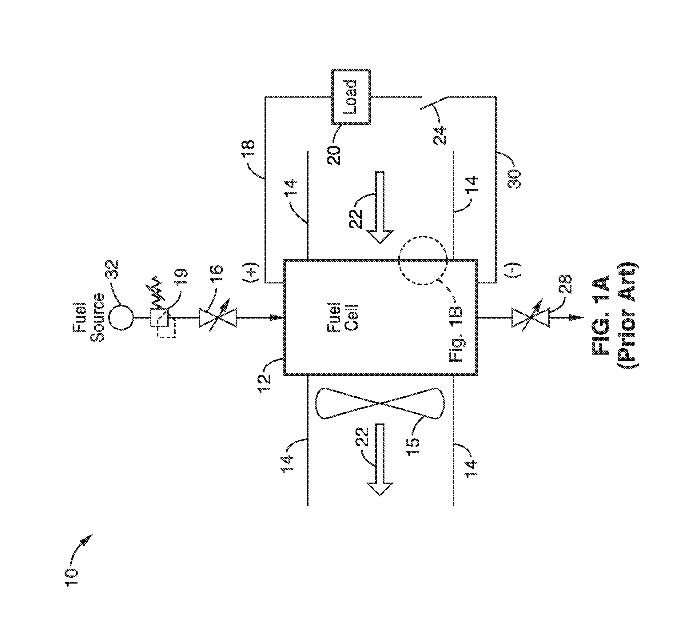
Over time, inert species such as nitrogen and water vapor accumulate in the anode chamber and impede the electrochemical reaction due to the interference of the mass transport of hydrogen to the anode electrodes.
This procedure leaves fuel within the anode volume, which allows the electrochemical reactions to continue within the fuel cell stack and creates a potential across the fuel cell stack, a potentially unsafe condition.
However, starting and stopping proton exchange membrane (PEM) fuel cell 12 is often detrimental to the platinum catalysts (not shown) used in PEM fuel cells, because h

Method used


Image

  • Integrated recirculating fuel cell system
  • Integrated recirculating fuel cell system
  • Integrated recirculating fuel cell system

Examples


embodiment 1

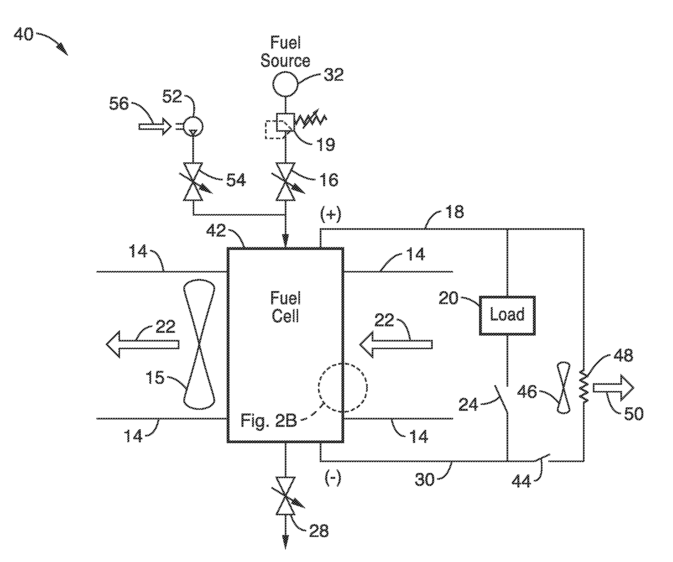
[0080]2. The fuel cell system of embodiment 1, wherein the auxiliary electrical load is located within said air duct to provide cooling air to said auxiliary electrical load.

[0081]3. A fuel cell system as recited in embodiment 1, further comprising: a purge air pump coupled to the fuel cell stack; wherein the a purge air pump is configured to provide purge air to the fuel cell stack upon stopping of the fuel cell system.

embodiment 2

[0082]4. The fuel cell system of embodiment 2, further comprising: one or more air dampers configured to control the flow of air within said air ducting.

embodiment 4

[0083]5. The fuel cell system of embodiment 4, further comprising: a recirculation return passage coupled to said fuel cell stack; wherein the recirculation return passage is configured to redirect air heated by the fuel cell stack back into the fuel cell stack, thereby providing heat for operation of the fuel cell stack.


PUM


Abstract

A PEM fuel system includes a fuel cell stack comprising one or more PEM fuel cells and fan configured to provide process air to supply oxidizer to and cool the fuel cell stack. The system has an air duct coupled to the fan and the fuel cell stack, and an electrical service load coupled to the fuel cell stack for receiving electrical power generated from reactions within the fuel cell stack. The system further includes as auxiliary electrical load coupled to the fuel cell stack and located within the air duct to reduce potentials across the fuel cell stack. The air duct is configured to direct the flow of air to the fuel cell stack and auxiliary electrical load to provide cooling air to the fuel cell stack and auxiliary electrical load.

Description

CROSS-REFERENCE TO RELATED APPLICATIONS[0001]This application claims priority from U.S. provisional patent application Ser. No. 61 / 444,595 filed on Feb. 18, 2011, incorporated herein by reference in its entirety.INCORPORATION-BY-REFERENCE OF MATERIAL SUBMITTED ON A COMPACT DISC[0002]Not ApplicableNOTICE OF MATERIAL SUBJECT TO COPYRIGHT PROTECTION[0003]A portion of the material in this patent document is subject to copyright protection under the copyright laws of the United States and of other countries. The owner of the copyright rights has no objection to the facsimile reproduction by anyone of the patent document or the patent disclosure, as it appears in the United States Patent and Trademark Office publicly available file or records, but otherwise reserves all copyright rights whatsoever. The copyright owner does not hereby waive any of its rights to have this patent document maintained in secrecy, including without limitation its rights pursuant to 37 C.F.R. §1.14.BACKGROUND OF...

Claims


Application Information

Patent Timeline
IPC IPC(8): H01M8/04H01M8/10H01M8/24
CPCH01M2008/1095H01M8/04014H01M8/04089Y02E60/50H01M8/04201H01M8/04238H01M8/2475H01M8/04097H01M8/04223H01M8/04225H01M8/04228H01M8/04302H01M8/04303H01M8/04H01M8/10H01M8/1018
Inventor GARRETTSON, GLEN A.GRUPP, DAVIDDABEL, JEREMY
Owner ALTERGY SYST
Why Eureka
Try Eureka