Sperm collector with squeezing function

Inactive Publication Date: 2012-08-23
AILV HEALTH TECH
View PDF78 Cites 13 Cited by
  • Summary
  • Abstract
  • Description
  • Claims
  • Application Information

AI Technical Summary

Benefits of technology

[0014]An advantage of the present invention is that: Since the pressing means is provided at a middle lower portion of the container body, the user could squeeze the penis insertion passage of the sperm collector by pressing the pressing means. Accordingly, stimulation to penis is increased and better effect of sperm collection is achieved, as compared with the sperm collectors according to the prior arts.
[0015]Another advantage of the present invention is that: The heating rod is provided in the middle of an inner wall of an end wall of the top end cover; the heating rod is inserted inside the penis insertion passage when the top end cover and the container body are engaged and the heating rod is removed from the penis insertion passage when the top end cover is disengaged. Structure of this kind could enable fast and convenient insertion of the heating rod inside the penis insertion passage of the sperm collector to heat up the sperm collector upon engagement of the top end cover, so as to overcome the disadvantage of causing discomfort to penis when currently existing sperm collector is used in an environment under relatively low temperature. Better effect of sperm collection could therefore be achieved. Also, structure of this kind is suitable for sperm collector in any shape.
[0016]A furthe

Problems solved by technology

Sperm collector in such a structure has the following disadvantages: Firstly, as the container body has a certain degree of hardness (to support the soft rubber body), the user is not able to press against an outer wall of the container body to squeeze the penis insertion passage of the soft rubber body received therein and therefore the stimulation effect on penis is n

Method used


Image

  • Sperm collector with squeezing function
  • Sperm collector with squeezing function
  • Sperm collector with squeezing function

Examples


Embodiment Construction

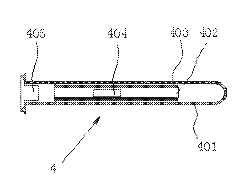
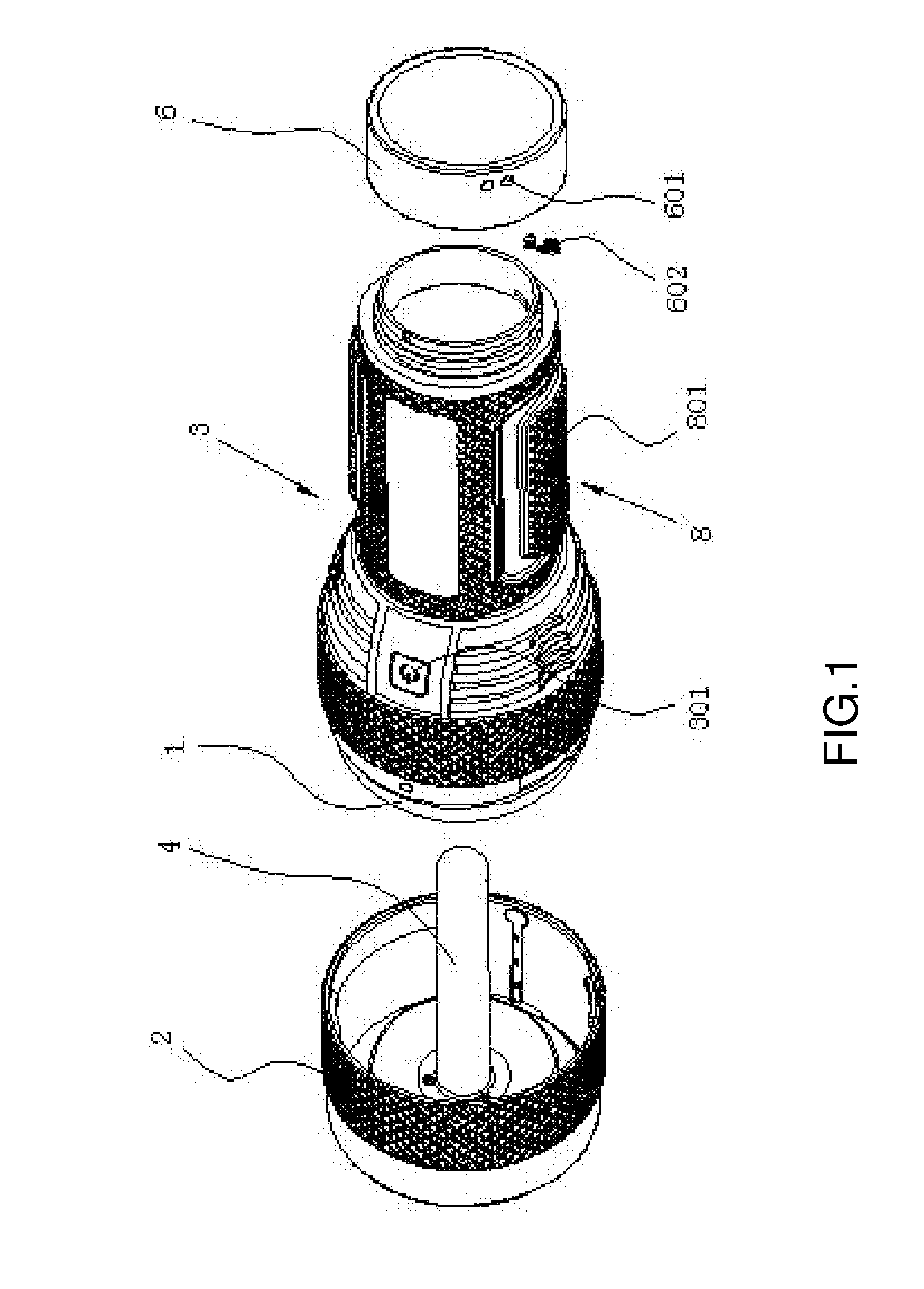
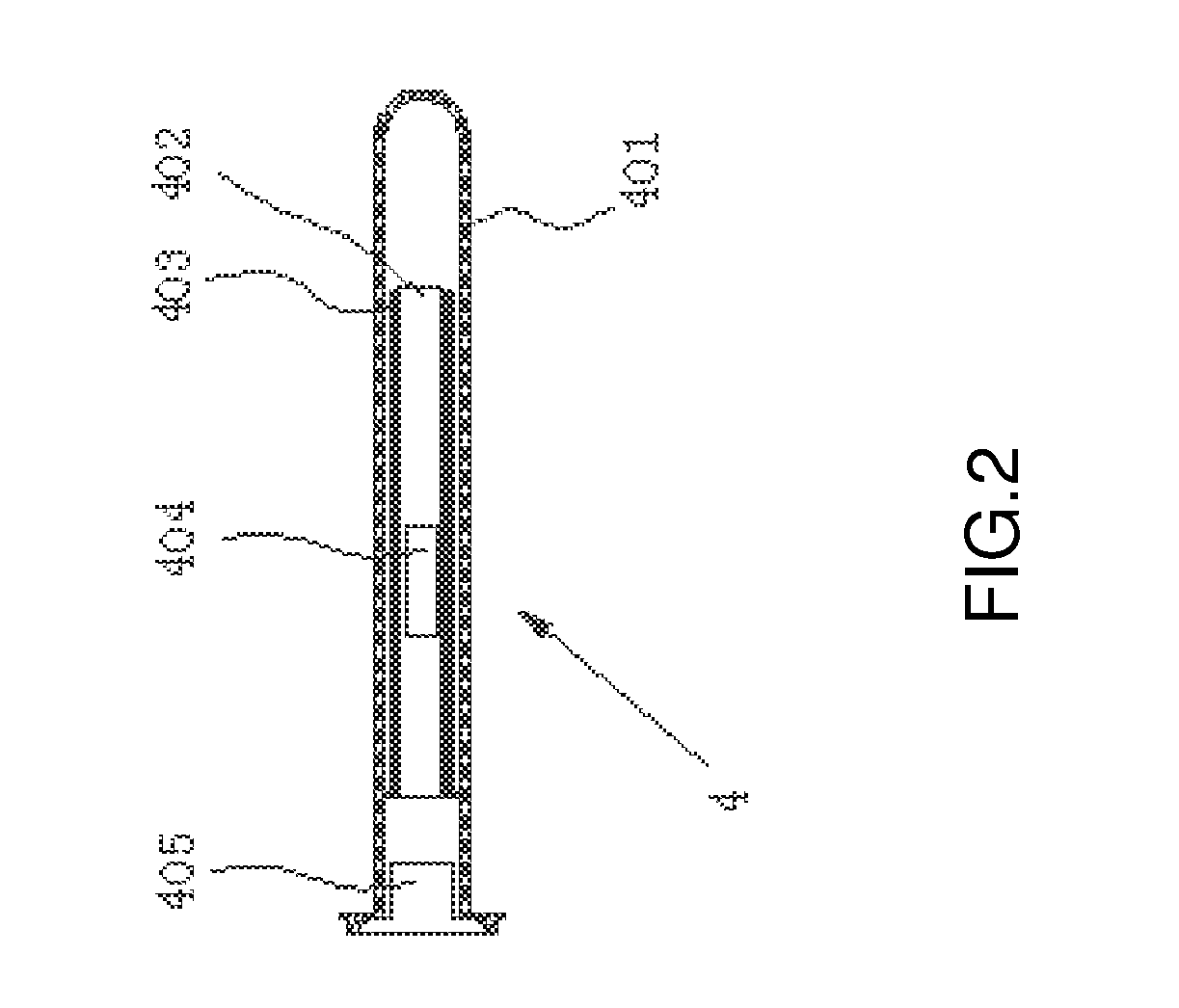
[0021]As shown in FIG. 1 to FIG. 4, a sperm collector with squeezing function according to the present invention comprises a soft rubber body 1 provided with a penis insertion passage, and a container body 3 which receives the soft rubber body 1. The container body 3 is disposed with a top end cover 2 at an upper end thereof, and a bottom end cover 6 at a bottom end thereof. When the top end cover 2, the bottom end cover 6 and the container body 3 are engaged, the soft rubber body 2 is confined within a cavity formed by the top end cover 2, the bottom end cover 6 and the container body 3. When the top end cover 2 is disengaged, a front end portion of the soft rubber body 2 protrudes out of an opening at the upper end of the container body 3. A pressing means 8 is provided at a middle lower portion of the container body 3. The container body 3 is preferably formed by connecting a large cylindrical body 302 and a small cylindrical body 303 both with circular cross sections; more speci...


PUM


Abstract

The present invention is a sperm collector with squeezing function. It includes a soft rubber body provided with a penis insertion passage and a container body provided with at least a top end cover and receives the soft rubber body. When the top end cover and the container body are engaged, the soft rubber body is confined within a cavity formed by the top end cover and the container body. When the top end cover is disengaged, a front end portion of the soft rubber body protrudes out of an opening of the container body. A pressing means is provided at a middle lower portion of the container body. When using the present invention, the user could press the pressing means to squeeze the penis insertion passage of the sperm collector. Accordingly, stimulation to penis is increased and better effect of sperm collection is achieved. In particular, since the present invention is also provided with a heating rod, lubricant pockets and electrical vibrators, which enable the user to reach a climax as quick as possible, thereby further enhancing the effect of sperm collection.

Description

BACKGROUND OF THE INVENTION[0001]The present invention relates to a sperm collector and more specifically relates to a sperm collector with squeezing function.[0002]Currently existing sperm collector mainly comprises a soft rubber body provided with a penis insertion passage and a container body provided with at least an end cover to receive the soft rubber body. When the end cover is closed, the soft rubber body is confined within a cavity formed by the end cover and the container body. When the end cover is opened, a front end portion of the soft rubber body protrudes out of the container body's opening so that a user of the sperm collector could grab the container body and uses the sperm collector directly. Sperm collector in such a structure has the following disadvantages: Firstly, as the container body has a certain degree of hardness (to support the soft rubber body), the user is not able to press against an outer wall of the container body to squeeze the penis insertion pass...

Claims


Application Information

Patent Timeline
IPC IPC(8): A61F5/453
CPCA61B10/0058A61F5/453A61F5/41A61H19/32A61H2201/105A61H2201/5082A61H2201/0228A61H19/00
Inventor WU, WEI
Owner AILV HEALTH TECH
Why Eureka
Try Eureka