
Method and apparatus for optimal enrichment of co2 for plant production

a technology for plant production and optimal enrichment, applied in soil-working methods, seed and root treatment, agriculture tools and machines, etc., can solve the problems of limiting the potential of indoor gardens to the amount (and lack of) available co2 in the climate of the grow room, plants can easily consume all of the co2 in an indoor garden in a matter of hours, and eventually stop, diminishing and eventually stopping

Inactive Publication Date: 2012-08-30
CURRIER DAVID FREDERICK
View PDF10 Cites 5 Cited by
  • Summary
  • Abstract
  • Description
  • Claims
  • Application Information

AI Technical Summary

Benefits of technology

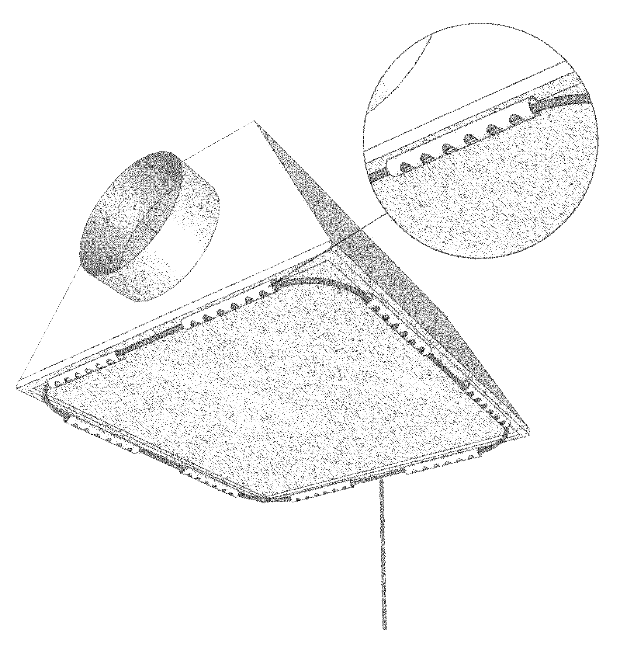
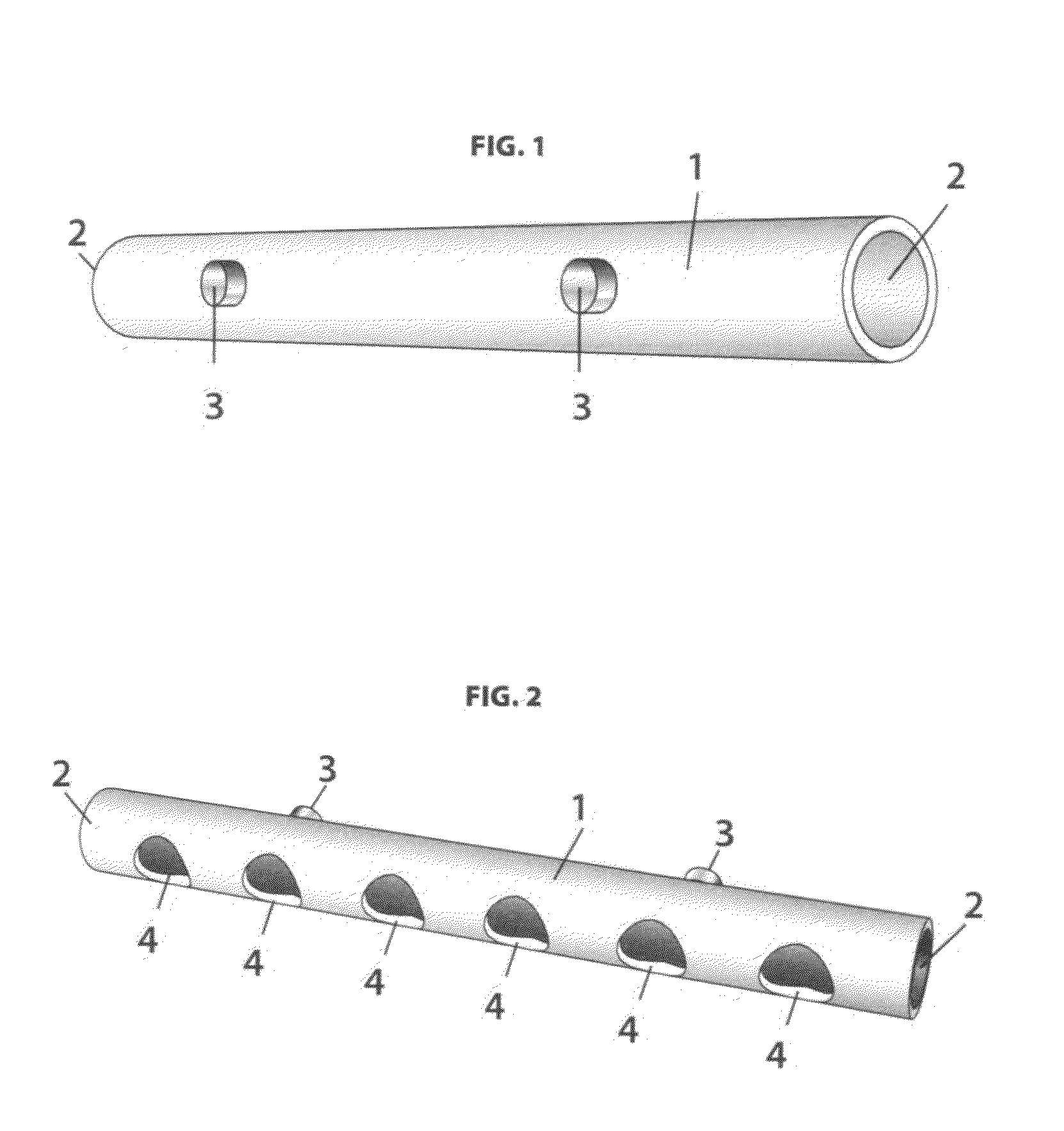
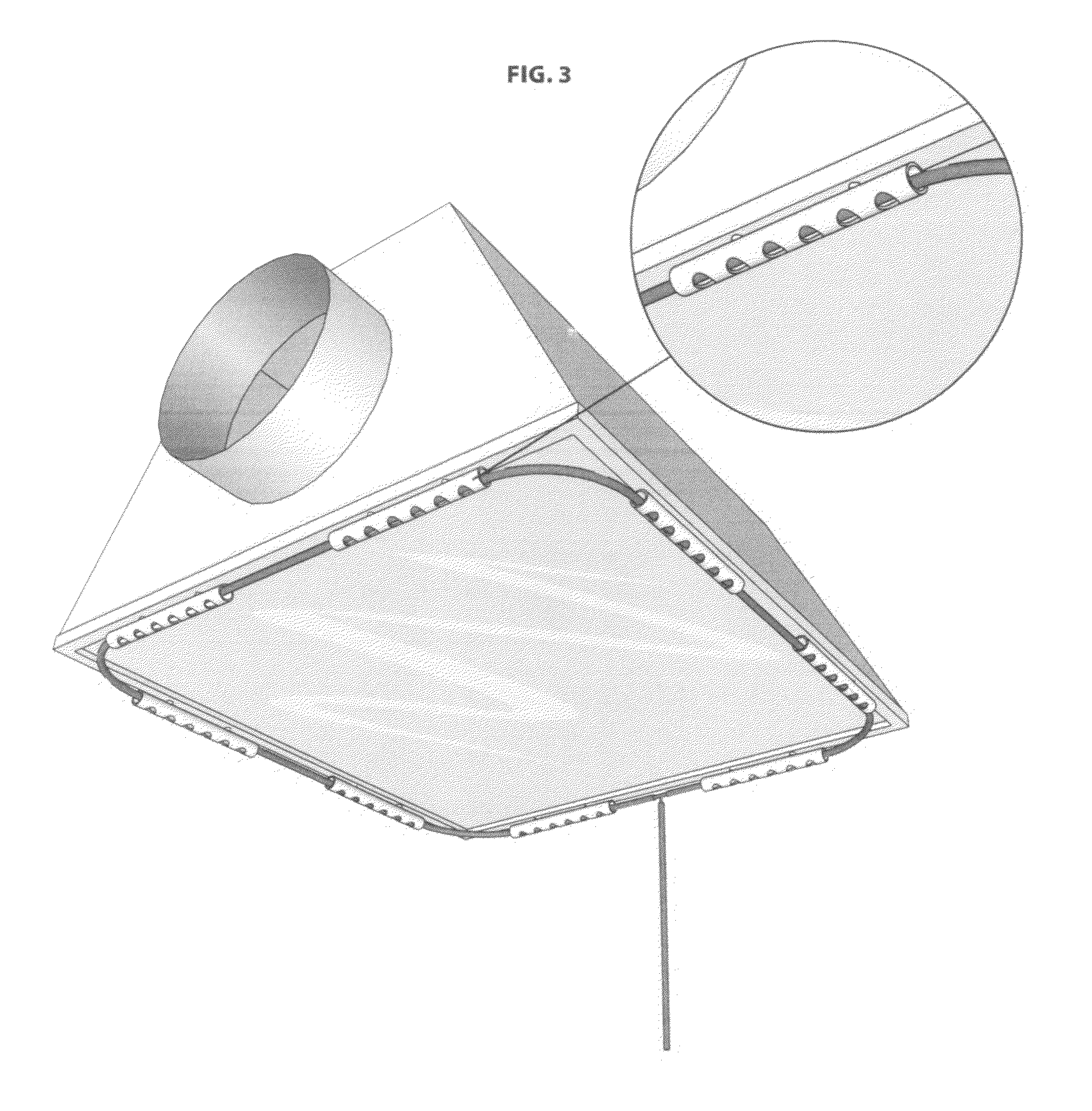
[0028]The present invention provides for CO2 tubing to be secured in a location between both the plant canopy and the lighting system within an indoor garden. Since it is known that CO2 is heavier than air, the present invention will have a various number of openings in the bottom of the apparatus, thus allowing the CO2 to be evenly dispersed directly over the optimal upper third portion of the plant canopy.
[0030]Few indoor gardeners actually achieve the goal of having a 100% sealed room, thus losing a % of the pricey CO2 each time the CO2 is dispersed throughout the “lights on” portion of the grow cycle. The present invention provides a method and apparatus that keeps the maximum amount of CO2 in the optimal upper third portion of the plant canopy, thus minimizing the amount of CO2 lost as a result of leakage in the indoor garden.
[0031]The average indoor garden is already cluttered with lights, light hanging kits and ventilation being suspended from the ceiling, resulting in setting up the currently preferred “distribution ring” method of securing CO2 tubing to be a highly difficult undertaking, and a method that is not possible without stressing plants that are currently growing. The present invention provides a method and apparatus for suspending CO2 tubing at the optimal distribution point that can be secured to any reflector (steel, aluminum, etc.) quickly, cleanly and does so in a manner that would not stress any plants that are currently growing.

Problems solved by technology

The major hurdle in achieving this goal is the fact that the average level of CO2 in the air is merely 300 PPM.
While the indoor gardening industry has experienced amazing advances in lighting, nutrients, pest control, cloning and hydroponics, the limiting factor in maximizing the potential of an indoor garden is the amount (and lack of) available CO2 in the grow room's climate.
At such a low level of 300 PPM in the air, plants can easily consume all of the CO2 in an indoor garden in a matter of hours.
Plants are only able to produce up to the limited amount of CO2 available, and once CO2 levels are 200 PPM or lower photosynthetic activity will diminish and eventually stop altogether.
Photosynthesis occurs only in the presences of light and is therefore useless, and even harmful to enrich the plants with CO2 during the dark (lights off) period of plant production.
Plants will also consume all of the available CO2 around their leaves within minutes.
With the labyrinth of cords and light hanging kits already suspended from the ceiling in an indoor garden, it becomes a difficult and time consuming task to properly construct this circular “distribution ring” of CO2 tubing.
It is known that for optimal CO2 enrichment, the CO2 should be evenly dispersed over the upper third portion of the plant canopy, but you are unable to accomplish this goal of optimal enrichment using the current “distribution ring” method of arranging CO2 tubing.
If plants are currently growing in the indoor garden, it is not possible to construct and secure the “distribution ring” in the preferred circular manner without stressing the plants.
In such situations, the preferred method of the “distribution ring” is even less effective since only a small percentage of the CO2 tubing will be suspended over the plant canopy.

Method used


Image

  • Method and apparatus for optimal enrichment of co2 for plant production
  • Method and apparatus for optimal enrichment of co2 for plant production
  • Method and apparatus for optimal enrichment of co2 for plant production

Examples


Embodiment Construction

[0027]The present invention provides CO2 to be dispersed from CO2 tubing at the optimal distribution point directly above the plant canopy for plant production.

[0028]The present invention provides for CO2 tubing to be secured in a location between both the plant canopy and the lighting system within an indoor garden. Since it is known that CO2 is heavier than air, the present invention will have a various number of openings in the bottom of the apparatus, thus allowing the CO2 to be evenly dispersed directly over the optimal upper third portion of the plant canopy.

[0029]While the CO2 tank system is the safest form of CO2 enrichment for indoor gardens, it is also the most expensive. Average CO2 cost is 0.50 cents per pound at most supply houses, and removing the heavy tanks from the indoor garden and having them refilled at welding supply stores is a chore that every user of the CO2 tank system hopes to do as few times as possible throughout each growing cycle.

[0030]Few indoor garden...


PUM


Abstract

The invention provides a method for optimal CO2 enrichment for plant production by suspending CO2 tubing in a secured position between both the plant canopy and lighting system within an indoor garden. The method provides for CO2 tubing to be secured to the lighting system of an indoor garden, thus allowing for the CO2 to be evenly dispersed directly over the optimal upper third portion of the plant canopy. By securing the CO2 tubing in the optimal distribution point, the invention also provides a method for users of the CO2 tank “timed release” system of CO2 enrichment to maximize the amount of CO2 over the upper third portion of the plant canopy during the limited time it is released in the indoor garden during the “lights on” portion of the grow cycle. The invention also provides an apparatus for carrying out the method.

Description

PROVISIONAL PATENT APPLICATION[0001]U.S. 61 / 464,048FEDERALLY SPONSORED RESEARCH[0002]Not ApplicableSEQUENCE LISTING OR PROGRAM[0003]Not ApplicableBACKGROUND OF THE INVENTION[0004]When CO2 levels are between 1000 and 1500 PPM, plants consume more light energy, base nutrients, water and oxygen to create a maximum rate of photosynthetic activity. This maximum rate of photosynthetic activity results in the astonishing plant yields all indoor gardeners strive for. The major hurdle in achieving this goal is the fact that the average level of CO2 in the air is merely 300 PPM. Plants are composed of 80-90% carbon and water, while most of the carbon in plants comes from the minimal 300 PPM level of CO2 in the air. While the indoor gardening industry has experienced amazing advances in lighting, nutrients, pest control, cloning and hydroponics, the limiting factor in maximizing the potential of an indoor garden is the amount (and lack of) available CO2 in the grow room's climate.[0005]Carbon ...

Claims


Application Information

Patent Timeline
Patent Type & Authority Applications(United States)
IPC IPC(8): A01G7/02
CPCA01G7/02
Inventor CURRIER, DAVID FREDERICK
Owner CURRIER DAVID FREDERICK
Learn More