Manufactured assembly and method for forming concrete foundations and walls

a technology of concrete foundations and manufactured components, applied in the direction of walls, building materials, constructions, etc., can solve the problems of high labor costs, higher equipment costs, lack of uniformity, and the cost of removing and disposing of forming panels, so as to reduce the lift of the form and fill the cavity of the foundation more efficiently

Inactive Publication Date: 2012-08-30
MCCARY JOHN M
View PDF4 Cites 3 Cited by
  • Summary
  • Abstract
  • Description
  • Claims
  • Application Information

AI Technical Summary

Benefits of technology

[0015]A running board or bar may be used to hold the wall forms from moving laterally and vertically from the footing assembly where the running board is fastened to the cross members of the footing form and then fastened in some fashion to the wall concrete form. The running board may be placed on both or one side of the wall form. Stakes, either driven or fastened to the poured upon surface and attached to the footing form, may be used to give lateral and vertical resistance when placed on either side of the footing form assembly. The combination of the attached running board and the stakes on the side(s) holds the footing and wall assembly from too much movement (lifting and settling) during concrete pouring. Flowable concrete is poured into the wall form and flows down into and filling the footing cavity. Usually during the pour the concrete in the footing cavity will be allowed to set for a short period of time during the pour before continuing the pour up into the wall form. By letting the footing concrete slightly set before continuing to pour helps control form lift. The foundation footing and the poured wall become a one monolithic structure with no cold joints between the wall and footing.
[0016]A third embodiment of this invention is a center insulated concrete wall form that may be placed upon the lattice panel footing form where the center insulated wall form is a manufactured assembly of a lattice panel attached to one side of rigid insulation foam with connecting cross members keeping the wall form lattice panel kept spaced apart and connected parallel to the rigid insulation foam. Either both wall form cavities can be poured at the same pouring with the footing form or one wall form lattice panel cavity can be poured with the footing. When the first poured wall cavity(s) is poured the footing cavity will be filled first with concrete and then allowed to sit for a short period of time during the pour to help reduce form lift. Then the wall cavity(s) will be filled to the desired height desired. Any bracing can then be removed from the non-poured cavity side and the remaining cavity poured. The structure interior facing or inside cavity of the center insulated foam concrete form is usually wider than the exterior cavity and the interior cavity when poured is usually load bearing though both poured cavities together add tension and compression strength to the wall.
[0017]Here again grid fingers or extensions of a section of the vertical lattice protrude outward on the exterior face of the vertical grid approximately ⅛th to 3 / 16ths inch to assist in holding the flow through concrete out past the lattice grid face of the panel to accumulate an adequate layer of concrete for smoothing and decorative treatment. Screeds extending out approximately ¼ inch from the exterior face of the lattice grid panel assist in smooth troweling and to create an adequate layer of concrete out from the lattice grid panel exterior face.
[0018]One advantage of being able to pour the wall form cavities at separate pours when using the center foam wall concrete form is that bracing can be put on the face side of the wall that is not to be poured. Then the wall bracing can be removed and the other cavity of the lattice wall form can be poured without the need for bracing since the first cavity poured and set gives enough strength to keep the wall straight in the second pouring. Also there is no bracing to get in the way of finishing the exterior surface of the second pour.
[0019]A second advantage of being able to pour the two cavities in separate pouring with a center insulated rigid foam wall concrete form is that an adjacent slab floor can be poured with the first or second pouring of the cavities of the wall form. Usually the slab would be poured with the same pouring as the wall cavity that is the exterior cavity (other side of center insulated foam concrete form) from the poured slab and both are usually the second pouring so that the usually wider interior cavity would fill the foundation footing cavity more efficiently.

Problems solved by technology

Problems associated with these processes include higher labor costs, higher equipment costs, lack of uniformity, and expense associated with the removal and disposal of the forming panels.
Also the difficulty of adding insulation within the concrete forms and the ability to perform exterior decorative treatments while maintaining a durable concrete exterior surface has been problematic in these concrete forming processes.
The biggest disadvantage of a two-stage pour is that it is more expensive than a monopour.
The cost to crane lift the tilt-up slab wall in place is expensive and the architectural style and look of tilt-up structures is fairly limited due to the nearly flat repeated slab panel construction.

Method used


Image

  • Manufactured assembly and method for forming concrete foundations and walls
  • Manufactured assembly and method for forming concrete foundations and walls
  • Manufactured assembly and method for forming concrete foundations and walls

Examples


Embodiment Construction

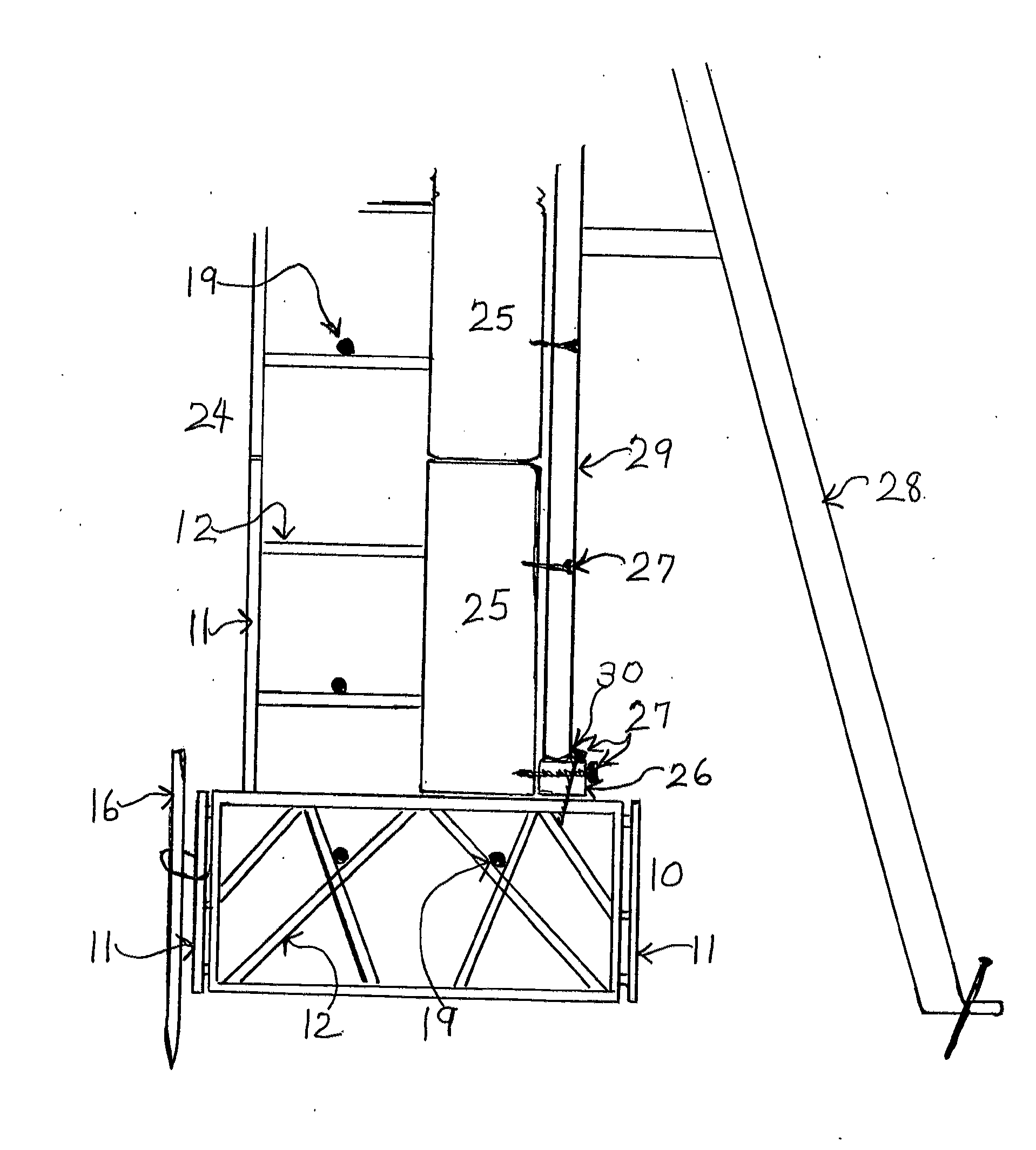
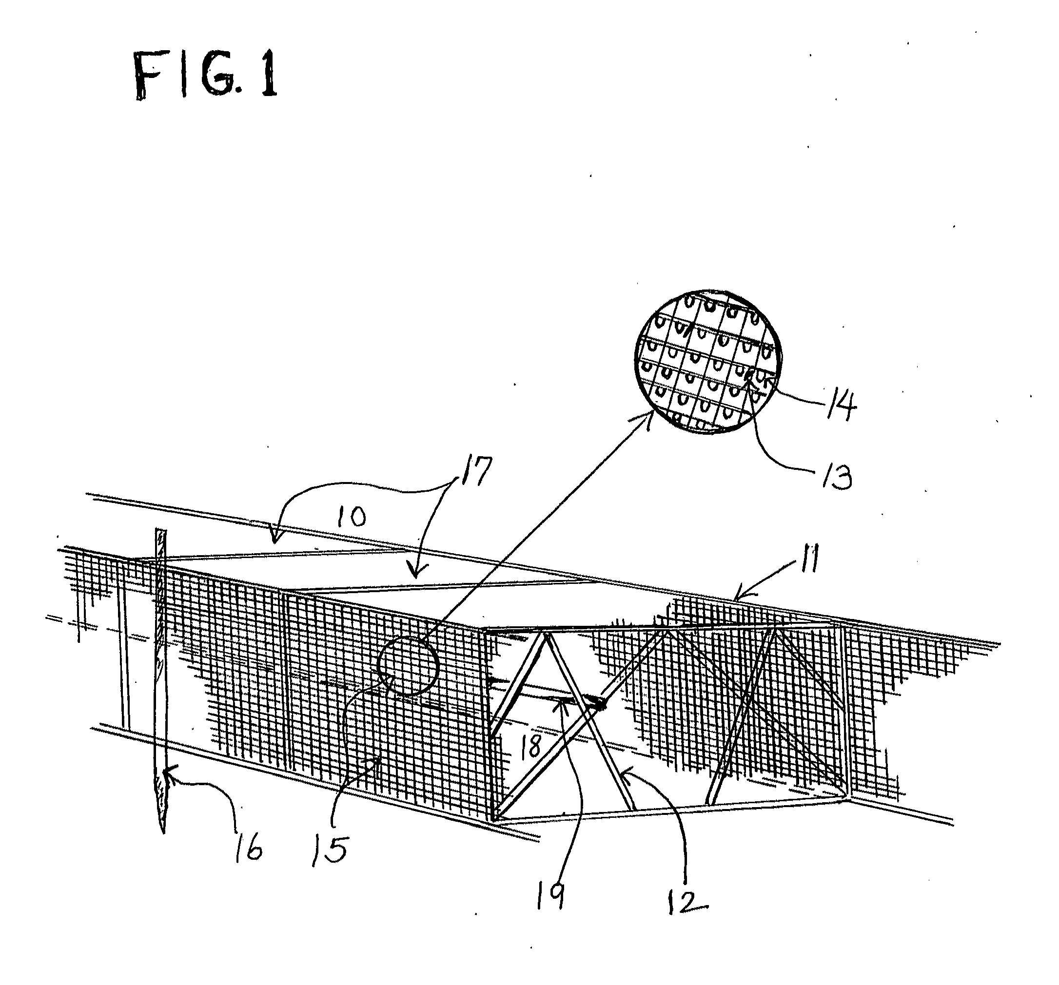
[0025]Referring now in more detail to the drawings in which the numerals indicate like parts throughout the several views, FIG. 1 shows in a perspective view a foundation footing form 10 that includes side parallel spaced apart lattice forming panels 11 and cross connecting members 12 that connect the two lattice forming panels 11 together. Troweling assisting guide screeds 13 and concrete accumulating grid fingers 14 are located upon the exterior face 15 of the lattice forming panels 11. Stakes 16 may be placed on either exterior side of the foundation footing form 10, helping to reduce lateral and possibly vertical movement of the form when concrete or cementous material 17 is poured into the footing form cavity 18. Rebar 19 is placed in the forming cavity 18 and usually rests on the cross connecting members 12.

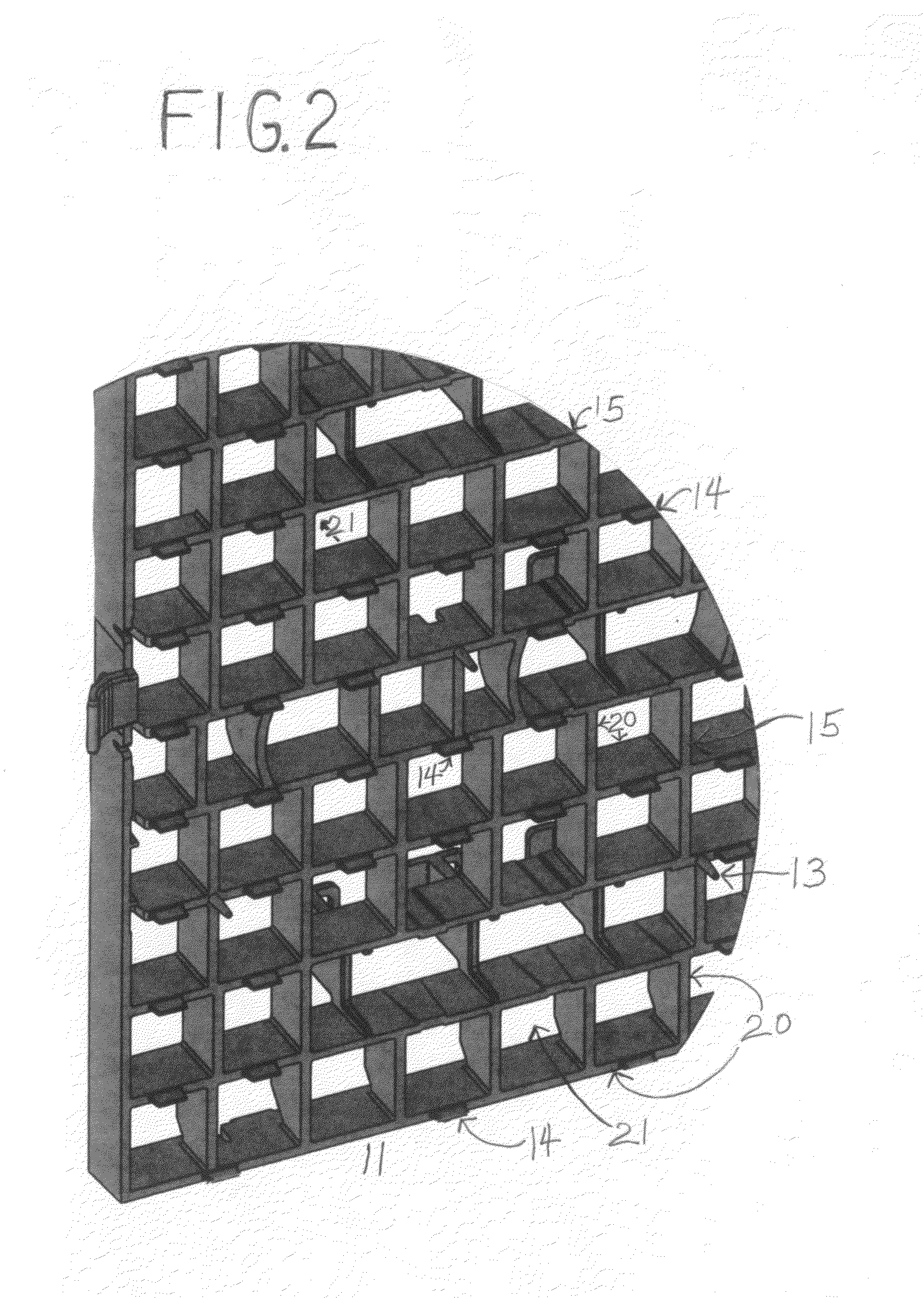
[0026]FIG. 2 shows in a perspective view the exterior face 15 of a lattice grid forming panel 11 with vertical and horizontal grids 20. Troweling assisting guide screeds 13...


PUM


Abstract

A manufactured assembly and method used to form poured concrete foundations and walls. The foundation and wall form's lattice grid exterior face holds adequate flow though concrete, with the assistance of the exterior grid fingers, for smoothing and decorative treatments and troweling is aided by lattice grid exterior screed guide points. The lattice grid panels, the lattice grid forming panel flow through concrete and the form cavity poured concrete become a substantially monolithic structure when the concrete is set and hardens dry. Rigid foam insulation is added to the center of a lattice grid paneled poured concrete wall form.

Description

CROSS-REFERENCED TO RELATED APPLICATIONS[0001]This application is a continuation-In-Part of application Ser. No. 12 / 198,973 filed Aug. 27, 2008.FIELD OF THE INVENTION[0002]This invention relates to the manufacturing assembly and method using flowing concrete or other cementous material to form poured concrete foundations and walls. This invention also relates to the concrete / cementous material flow through and accumulation on the lattice grid panel of a concrete form to create an adequate concrete layer on the external surface of the panel for effective smoothing and decorative finish. This invention further relates to insulated poured concrete walls.BACKGROUND OF THE INVENTION[0003]The process of constructing a poured concrete foundation and wall has conventionally required forms to be created on site, wherein the concrete forms may consist of wood, metal, plastic or wood / metal panels erected and maintained in spaced, parallel relationship with other panels. Fluid concrete is then ...

Claims


Application Information

Patent Timeline
Patent Type & Authority Applications(United States)
IPC IPC(8): E04G21/02E04B2/84E02D27/00
CPCE02D27/00
Inventor MCCARY, JOHN M.
Owner MCCARY JOHN M
Why Eureka
Try Eureka