
Power plant for co2 capture

a power plant and co2 technology, applied in the direction of machines/engines, mechanical equipment, separation processes, etc., can solve the problems of increasing the complexity of the plant and plant operation, and difficulty in retrofitting co2 capture equipment into an existing power plant or power plant concept, so as to optimize the overall operation of the power plant

Inactive Publication Date: 2012-08-30
GENERAL ELECTRIC TECH GMBH
View PDF12 Cites 7 Cited by
  • Summary
  • Abstract
  • Description
  • Claims
  • Application Information

AI Technical Summary

Benefits of technology

[0013]A method for operating a power plant is disclosed mixing flue gas flow paths of a power part and a CO2 power part via a flue gas system into a mixed flue gas; removing via a CO2 capture system, CO2 from the mixed flue gas, wherein the power part is a fossil fuel fired steam power plant or a gas turbine based power plant, and wherein the CO2 power part

Problems solved by technology

Known technologies for CO2 capture and compression can require relatively large amounts of energy.
However they can increase the complexity of the plant and plant operation.
Further, complex integrated solutions can render it difficult to retrofit CO2 capture equipment into an existing power plant or power plant concept.

Method used


Image

  • Power plant for co2 capture
  • Power plant for co2 capture
  • Power plant for co2 capture

Examples


Embodiment Construction

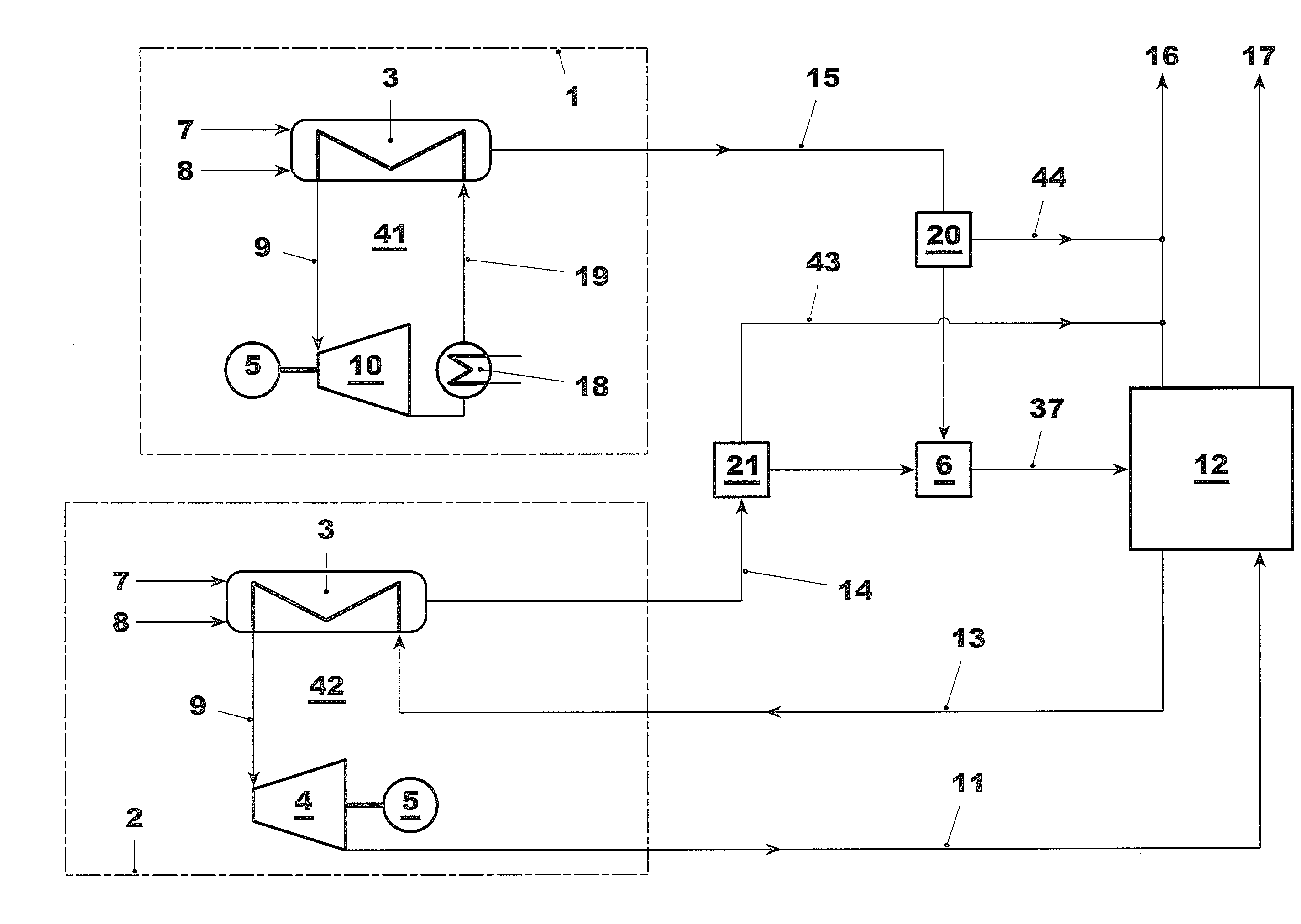
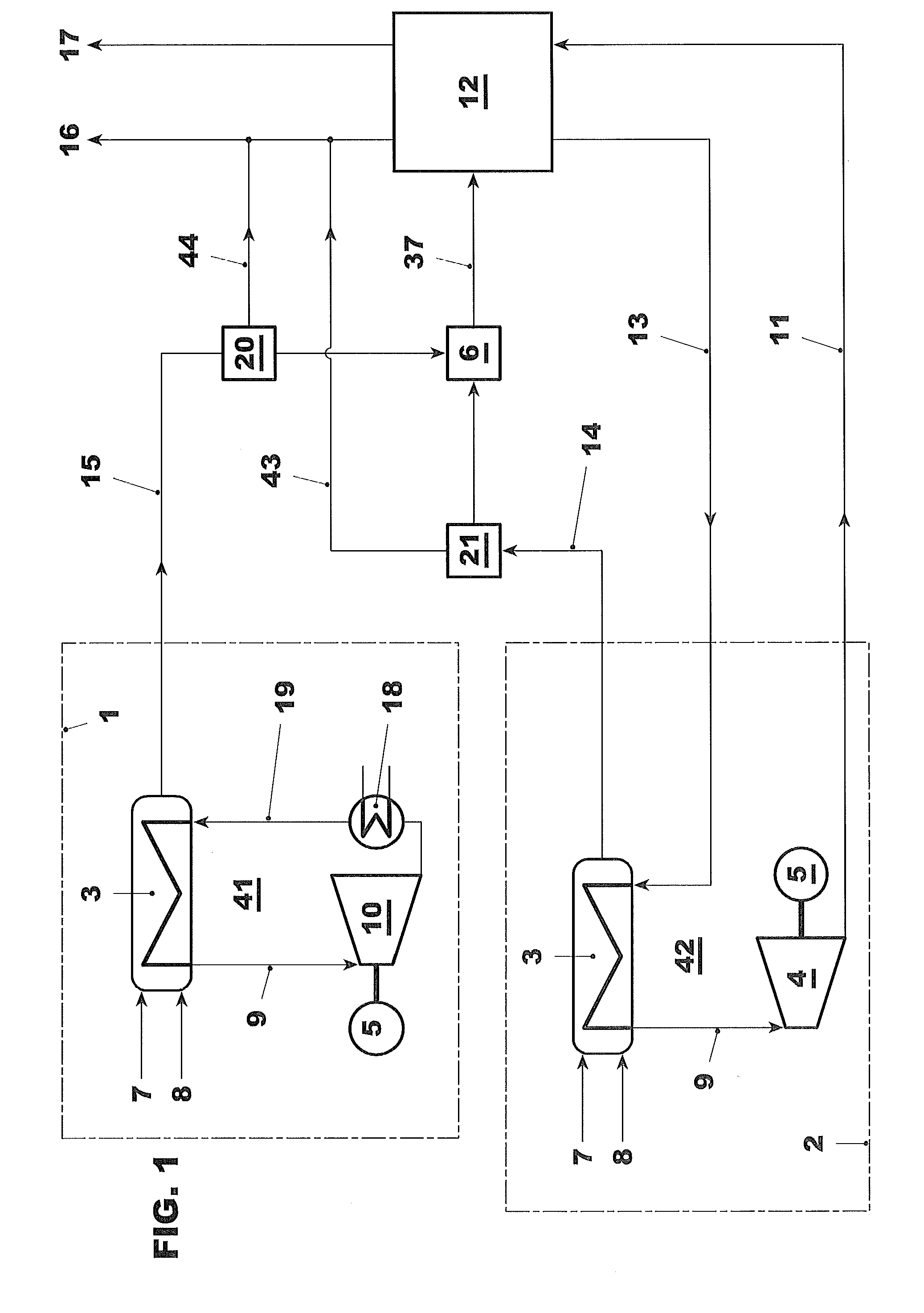
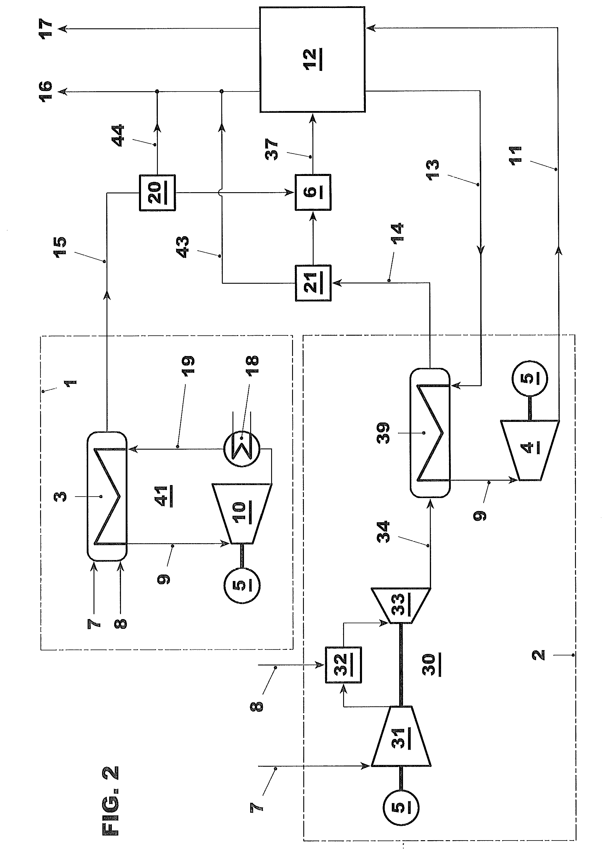
[0022]The present disclosure provides a fossil fuel fired power plant with minimum impact of the CO2 capture system (also called CO2 capture plant) on the plant as well as a method to operate such a plant. Further, a power plant, which is ready for the retrofit of a CO2 capture plant and a method to retrofit an existing plant into a power plant with CO2 capture as well as a method to operate this kind of plant.

[0023]According to an exemplary embodiment of the disclosure, a plant can include at least two parts. A plant including at least one part, which is basically designed like a known power plant without CO2 capture, at least one additional fossil fuel fired power plant part, plus at least one CO2 capture system designed to capture CO2 from the flue gases of the plant part and of the additional CO2 power plant part. The known part of the power plant is called the power part. The additional power plant part is called CO2 power part.

[0024]An exemplary embodiment of the disclosure pr...


PUM


Abstract

An exemplary fossil fuel fired power plant is disclosed with minimum impact of the CO2 capture system on a power part of the plant. A power plant is disclosed which is ready for the retrofit of a CO2 capture plant, and a method is disclosed for retrofitting an existing plant into a power plant with CO2 capture. A power plant part is disclosed which can provide steam and power to operate CO2 capture system, and provide a CO2 capture system, which has the capacity to remove CO2 from flue gas flow of the power part, and of the additional power plant part.

Description

RELATED APPLICATION(S)[0001]This application claims priority as a continuation application under 35 U.S.C. §120 to PCT / EP2010 / 063848, which was filed as an International Application on Sep. 21, 2010 designating the U.S., and which claims priority to European Application 09171635.7 filed in Europe on Sep. 29, 2009. The entire contents of these applications are hereby incorporated by reference in their entireties.FIELD[0002]The disclosure relates to power plants with integrated CO2 capture as well as CO2 capture ready power plants.BACKGROUND INFORMATION[0003]Generation of greenhouse gases can lead to global warming and further increases in greenhouse gas production will further accelerate global warming. Because CO2 (carbon dioxide) is identified as a greenhouse gas, carbon capture and storage is considered one potential means to reduce the release of greenhouse gases into the atmosphere and to control global warming. In this context CCS can be defined as the process of CO2 capture, c...

Claims


Application Information

Patent Timeline
IPC IPC(8): F01N3/00F02C3/00F01D1/00F02C3/34
CPCB01D53/62F01K23/10F02C6/18Y02E20/16Y02C10/04Y02C10/06Y02E20/14F05D2260/61Y02E20/32Y02A50/20Y02C20/40
Inventor LI, HONGTAONAGEL, HOLGER GERHARDMAHIEUX, CELINEDROUX, FRANCOIS
Owner GENERAL ELECTRIC TECH GMBH
Learn More