RFID tag assembly and method

Inactive Publication Date: 2012-08-30
TAGSYS
View PDF9 Cites 82 Cited by
  • Summary
  • Abstract
  • Description
  • Claims
  • Application Information

AI Technical Summary

Benefits of technology

[0005]The present invention may provide a two part tag solution, namely an RFID tag assembly including an associated or primary antenna formed with means for attaching the assembly to a material such as fabric or cardboard. In some embodiments the primary antenna may couple to a secondary antenna provided on or with the material. This solution may be particularly useful since use of ultra high frequency (UHF) as a carrier frequency for RFID t

Problems solved by technology

However this often leads to a bulky and inflexible solution parti

Method used


Image

  • RFID tag assembly and method
  • RFID tag assembly and method
  • RFID tag assembly and method

Examples


Embodiment Construction

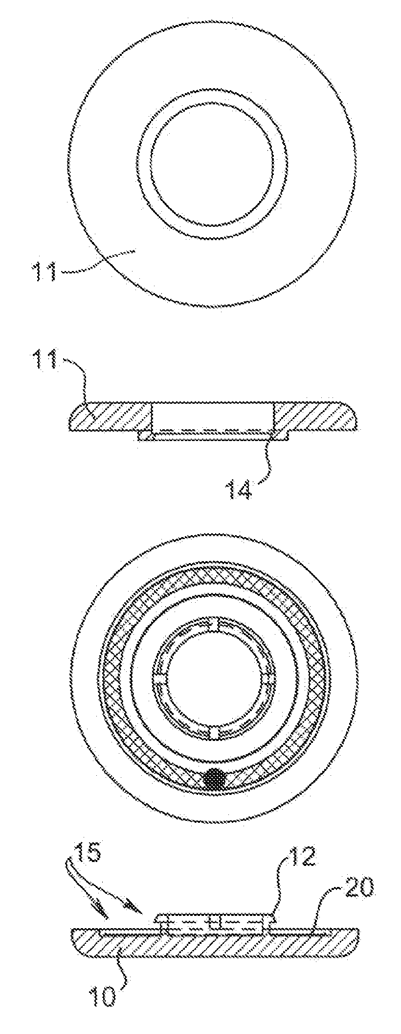
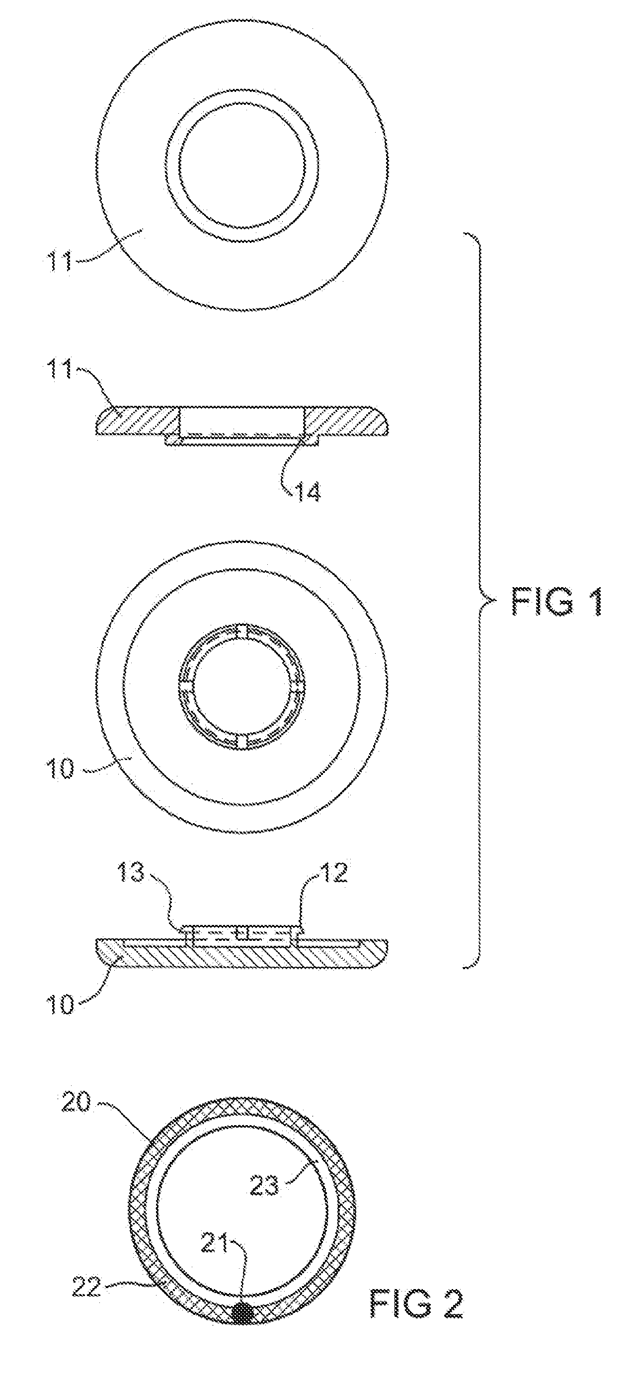
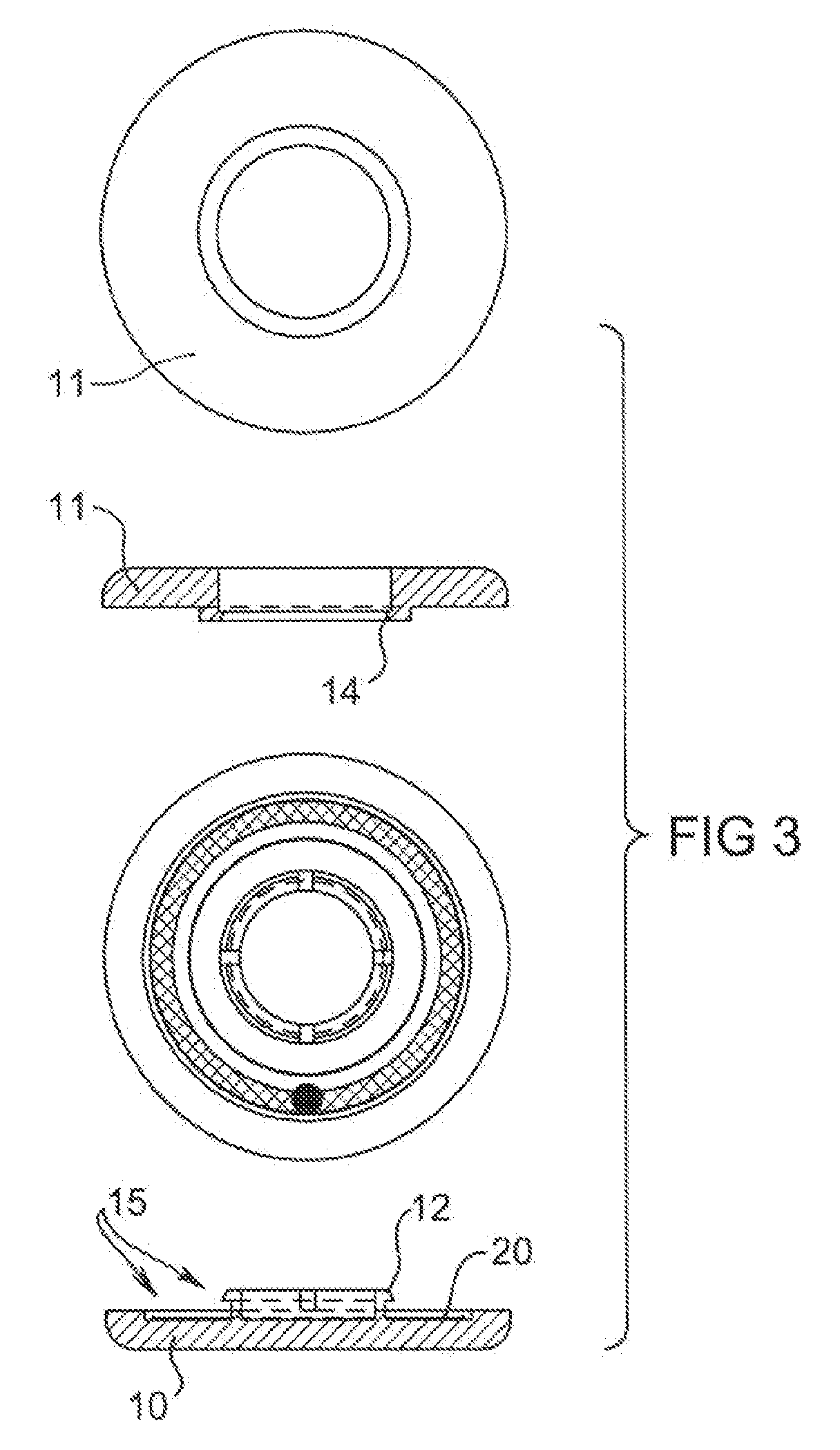
[0041]Referring to FIG. 1 an RFID rivet is formed in two parts, a disc part or rivet plug 10 which snap locks into a rectangular toroid part or rivet ring 11. The rivet plug 10 includes a smaller diameter raised tubular part 12 with an external barb 13 which mates to an internal barb recess 14 of a larger diameter raised tubular section of rivet ring 11 to provide a snap locking mechanism.

[0042]Referring to FIG. 2, RFID tag 20 includes a primary antenna and RFID chip 21 bonded to a conductive track 22 formed on an insulating substrate 23. Insulating substrate 23 comprises a rectangular toroid shape and may be die cut from a continuous web of complete RFID tags.

[0043]Referring to FIG. 3, RFID tag 20 is placed over the raised tubular part 12 of rivet plug 10 and into an annular recess 15 of rivet plug 10 which is on the same side as raised tubular part 12, the recess 15 having larger outside and smaller inside diameters than the corresponding diameters of RFID tag 20. RFID tag 20 has ...


PUM

PropertyMeasurementUnit
Thicknessaaaaaaaaaa
Flexibilityaaaaaaaaaa
Electrical conductoraaaaaaaaaa

Abstract

A method is disclosed of producing an RFID tag assembly including an associated antenna and attachment means suitable for attaching the tag assembly to a material. The material may be flexible such as fabric or relatively rigid such as cardboard. The method includes forming the associated antenna and the attachment means as a unitary conductive frame. An RFID tag assembly produced by the method is also disclosed.

Description

BACKGROUND OF THE INVENTION[0001]The present invention relates to an RFID tag assembly and method for producing the tag assembly. The tag assembly includes an associated antenna and an attachment means for attaching the assembly to a material. The material may be flexible such as fabric or it may relatively rigid such as cardboard. In a preferred embodiment the invention may include a rivet containing a radio frequency identification (RFID) tag. In some embodiments the tag may be applied to the material in the vicinity of a structure present on the material which structure may function as a secondary antenna.THE PRIOR ART[0002]Use of a generic RFID tag on material such as fabric typically involves stitching the tag directly to the fabric or enclosing it within a patch to provide an enclosure for the tag. However this often leads to a bulky and inflexible solution particularly with a clothing garment that may be uncomfortable to wear.[0003]In one prior art solution, a conductive thre...

Claims


Application Information

Patent Timeline
IPC IPC(8): G06K19/077H01Q1/12
CPCG06K7/10178G06K19/02G06K19/027G06K19/041G06K19/07749Y10T29/49018G06K19/07758H01Q1/12H01Q1/2225H01Q1/273H01Q9/16G06K19/07756
Inventor MARTIN, PHILIPPEHALL, DAVID MALCOLM
Owner TAGSYS
Why Eureka
Try Eureka