
Wind turbine blade, wind turbine generator with the same, and design method of wind turbine blade

Inactive Publication Date: 2012-08-30
MITSUBISHI HEAVY IND LTD
View PDF7 Cites 12 Cited by
  • Summary
  • Abstract
  • Description
  • Claims
  • Application Information

AI Technical Summary

Benefits of technology

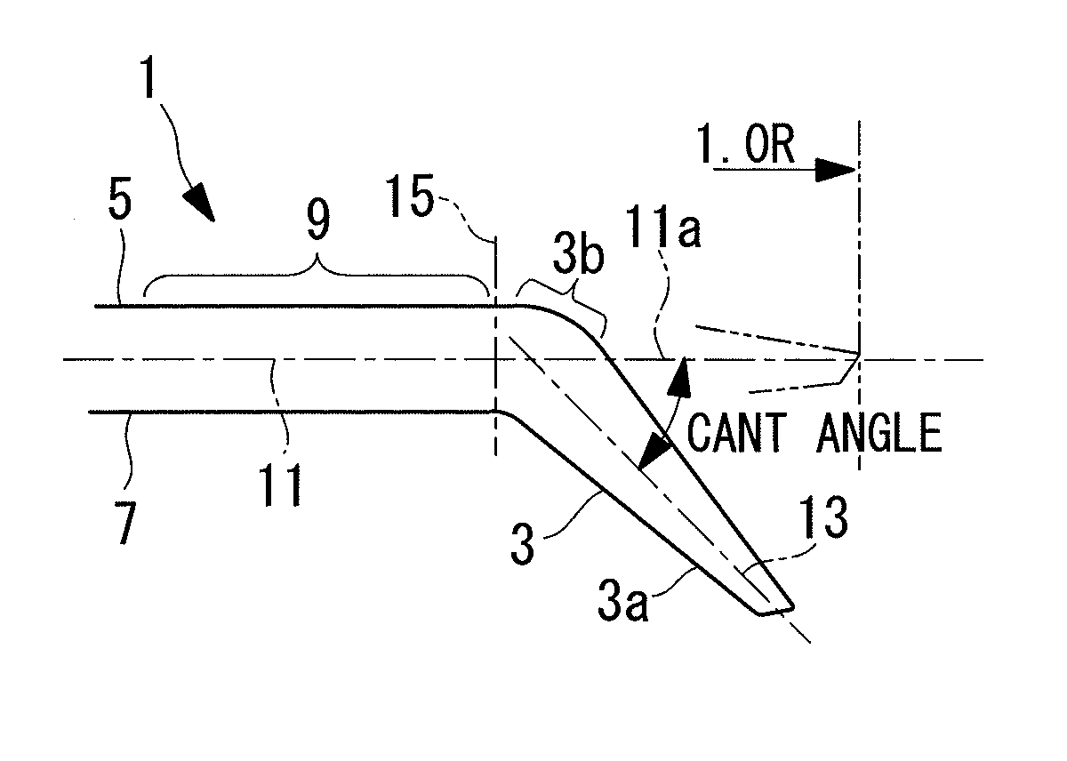
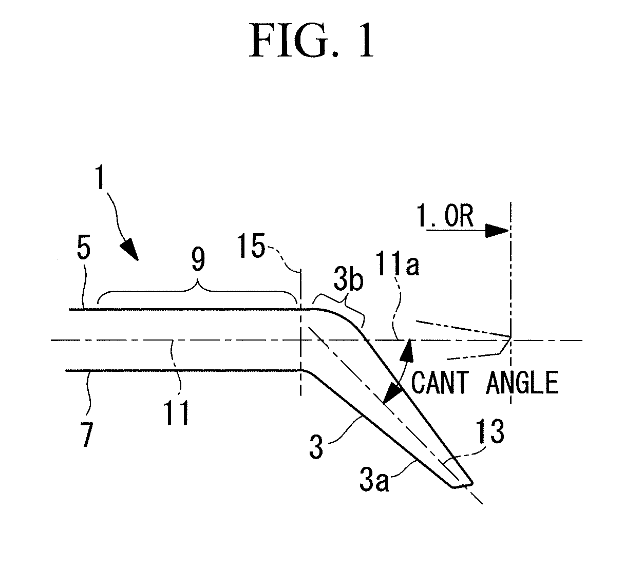
[0032]According to the present invention, the CANT angle of the winglet is configured to be 15° or more and 55° or less, so that swirls on the blade tip are reduced, thereby enhancing the performance (torque generated by the wind turbine blade) and / or reducing the moment (load) caused on the blade root.

Problems solved by technology

Actually, the upper limit of blade efficiency is approximately 0.5 because of (1) efficiency loss due to swirl (rotation) of a blade wake, (2) efficiency loss due to air resistance on a blade section, and (3) efficiency loss due to a wing tip vortex.
Therefore, there is a conflict relationship between the above (1) and the above (2), and it is difficult to cope with both.

Method used


Image

  • Wind turbine blade, wind turbine generator with the same, and design method of wind turbine blade
  • Wind turbine blade, wind turbine generator with the same, and design method of wind turbine blade
  • Wind turbine blade, wind turbine generator with the same, and design method of wind turbine blade

Examples


Embodiment Construction

[0038]Hereinafter, descriptions will be provided on the embodiment according to the present invention with reference to the drawings.

[0039]The wind turbine blades according to the present embodiment are preferably used as blades of a wind turbine generator. The wind turbine blades are configured to be three dimensional blades and include three blades, for example, which are respectively coupled to a rotor at 120° intervals. Each wind turbine blade preferably has a rotational diameter (blade diameter) of 60 m or more, and is a slender blade whose solidity is 0.2 or more and 0.6 or less. The wind turbine blade may have a variable pitch or a fixed pitch.

[0040]FIG. 1 illustrates a tip of the wind turbine blade 1 provided with a winglet 3. This drawing is a front view of the wind turbine blade viewed from the leading edge thereof, and a suction side of the blade (suction surface) 5 is located on the upper side and a pressure side of the blade (static pressure surface) 7 is located on the...


PUM


Abstract

Provided is a wind turbine blade realizing enhancement of performance by a winglet provided at a blade tip. The wind turbine blade includes the winglet formed by bending a tip side thereof toward a pressure side of the blade relative to an adjacent portion adjacent on a blade root side, and a CANT angle defined by a blade axial line of the winglet relative to a radial extrapolation line of a blade axial line of the adjacent portion is set to be 15° or more and 55° or less. The winglet includes a tip end located on a tip side thereof, having a substantially linear blade axial line, and a bent portion located on a base end side of the winglet and bent relative to the adjacent portion. This bent portion is bent gradually so as to satisfy the predetermined CANT angle.

Description

CROSS-REFERENCE TO RELATED APPLICATIONS[0001]This application is based on Japanese Patent Application No. 2011-043188, the contents of which are incorporated herein by reference.TECHNICAL FIELD[0002]The present invention relates to a wind turbine blade, a wind turbine generator with the same, and a design method of a wind turbine blade.BACKGROUND ART[0003]Recently, a wind turbine generator has attracted people's attention as clean energy that does not emit greenhouse effect gas when generating power. A wind turbine generator rotates wind turbine blades around its axis by wind and converts this rotation force into electric power so as to attain power output.[0004]Power output of a wind turbine generator is expressed by a product of shaft end output (output generated by blades) and conversion efficiency (efficiencies of bearings and a generator, and the like). The shaft end output is expressed by the following formula, and a blade having high blade efficiency and a greater diameter en...

Claims


Application Information

Patent Timeline
IPC IPC(8): F03D9/00G06F17/50F03D1/06
CPCF03D1/0633Y02E10/721G06F17/50F05B2240/30F03D1/0675G06F30/00Y02E10/72F05B2240/307
Inventor FUKAMI, KOJI
Owner MITSUBISHI HEAVY IND LTD
Learn More