Acceleration mechanism for exercise equipment

a technology of acceleration mechanism and exercise equipment, which is applied in the direction of machines/engines, gymnastics, gearing, etc., can solve the problems of only being able to achieve exercise, becoming very extravagant, and troublesome for users, so as to reduce overall volume and weight, and generate large braking power

Inactive Publication Date: 2012-08-30
BION
View PDF25 Cites 26 Cited by
  • Summary
  • Abstract
  • Description
  • Claims
  • Application Information

AI Technical Summary

Benefits of technology

[0028](9) The acceleration mechanism may be coupled with a brake device. The brake device may be rotated in a high speed, so that the brake device may generate large braking power with reduced overall volume and weight.

Problems solved by technology

Population is gradually concentrated in large cities and under such a condition that a great population resides in a limited area, it becomes very extravagant to provide a large amount of space for doing exercise.
Even in a public place, doing exercise may only be achieved by spending money and time.
This is troublesome for users.
This is effective in reducing the speed of the flywheel or in other words increasing the resistance of the flywheel, but the brake shoe is gradually worn out.
Further, for a long time use, the brake shoe generates high temperature and thus releases odors, as well as noises.
Such a conventional structure has drawbacks including: large volume, small amount of power generated in low rotational speed, great waste of material cost, high temperature in operation, being hard to assemble, and high human labor cost.
Such a conventional structure has disadvantages, which include: requiring a complicated gear based structure that is composed of various gears and toothed wheels, high material costs, great noise generated in the operation of the gears, being hard to assemble, high human labor cost, speed magnification being limited by the structure.
Such a conventional structure is advantageous for being of a small size, but it also has disadvantages including: small amount of power generated in low rotational speed, great waste of material cost, being hard to assemble, and high human labor cost.
Such a conventional shows certain drawbacks, including: requiring an externally mounted power generation module, being hard to assemble, high material costs, high human labor cost, and difficult maintenance.
All these various known techniques are effective in generating electricity, inducing a brake power, and achieving the purpose of doing exercise, but they are complicated structures and the sizes are generally bulky, making it impossible to effectively make use of a limited amount of space.

Method used


Image

  • Acceleration mechanism for exercise equipment
  • Acceleration mechanism for exercise equipment
  • Acceleration mechanism for exercise equipment

Examples


first embodiment

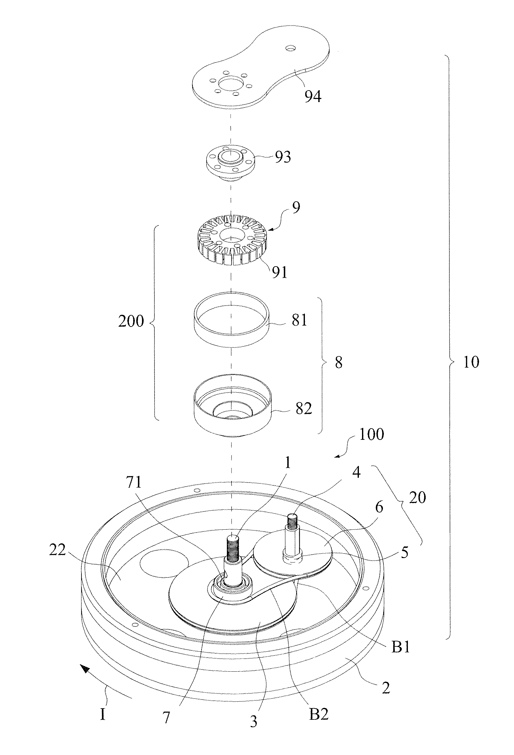
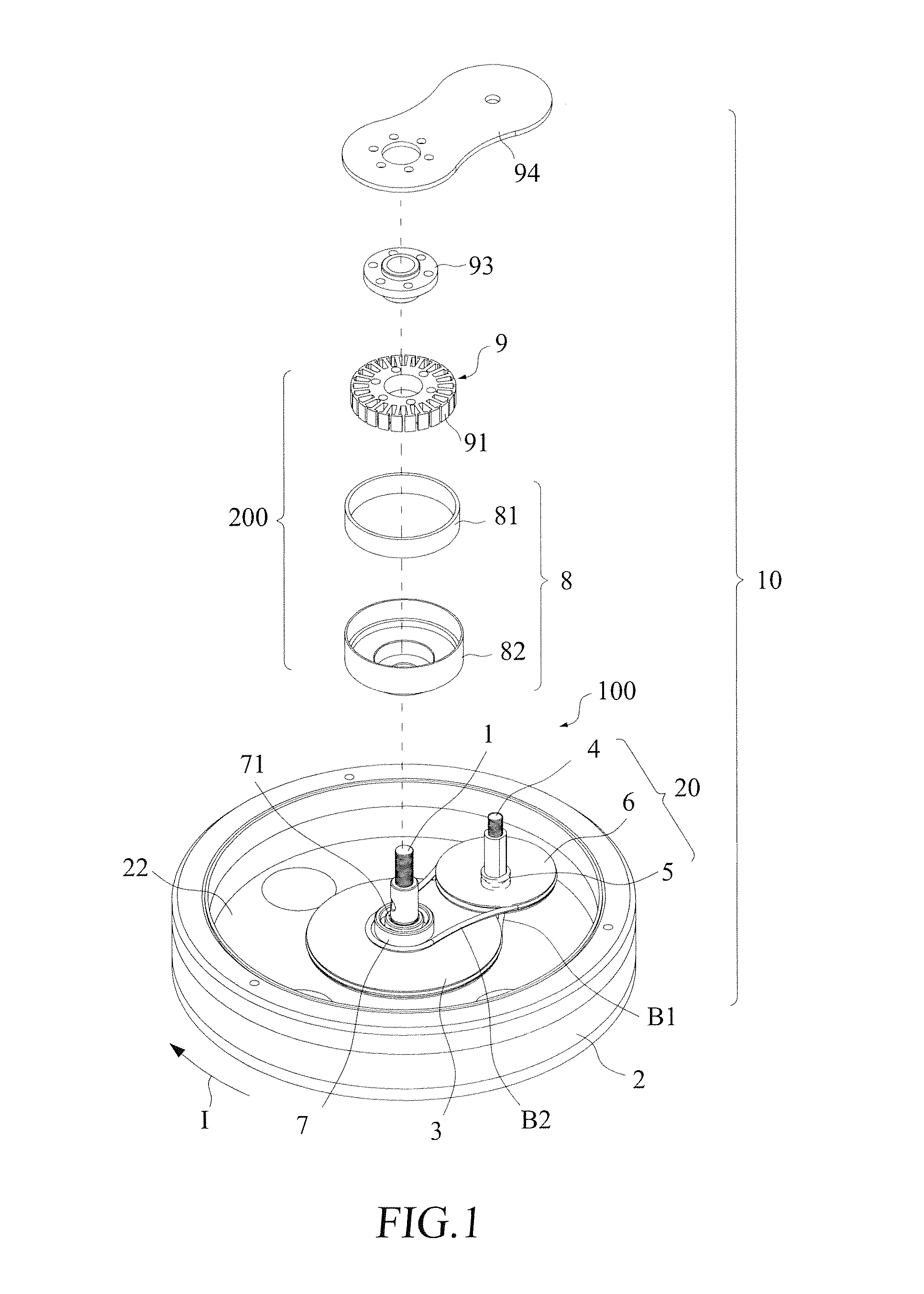
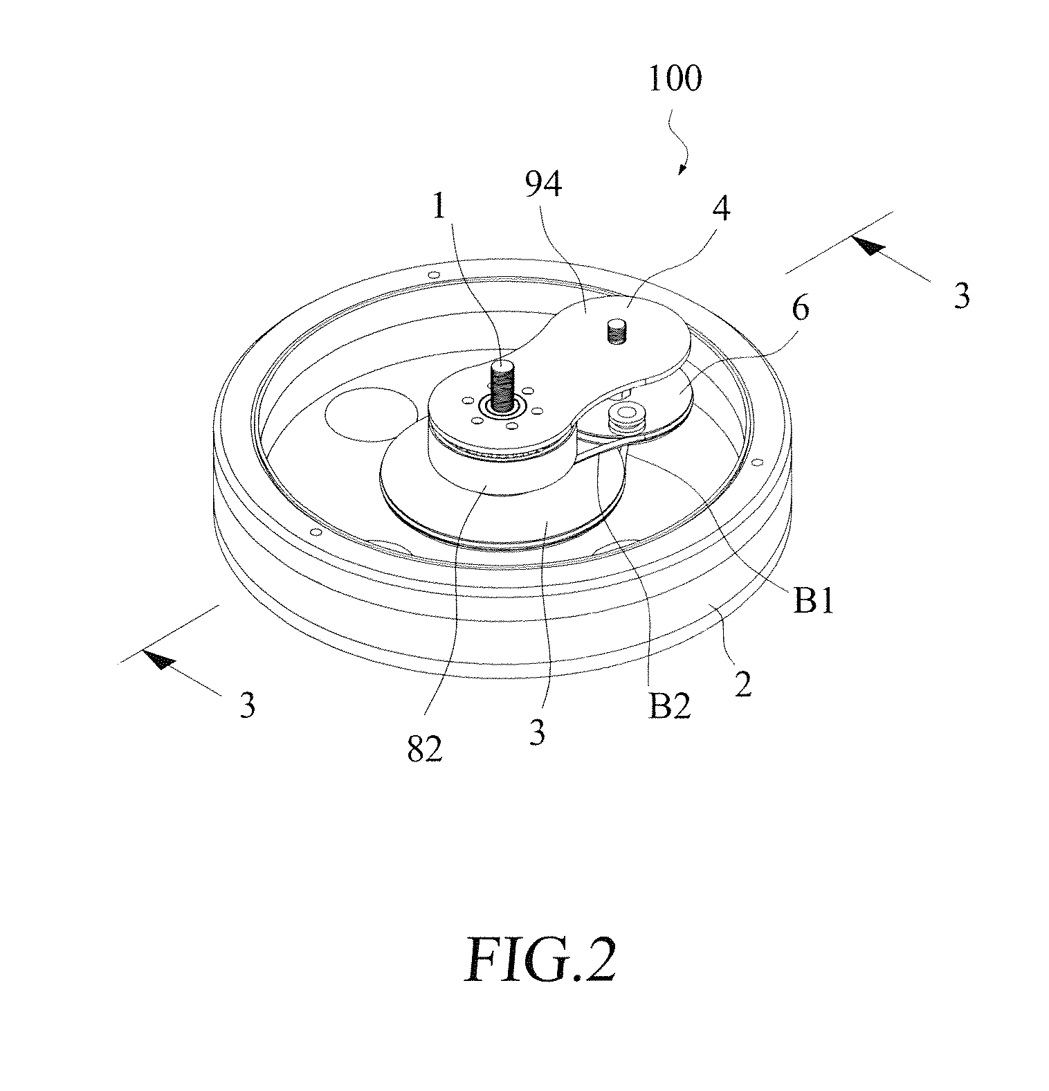
[0044]With reference to the drawings and in particular to FIGS. 1-3, a rotary disk acceleration device, generally designated at 10, according to the present invention is provided for exercise equipment, comprising generally a rotary disk acceleration mechanism 100 and a power generation module 200. The rotary disk acceleration mechanism 100 comprises a stationary axle 1 and a flywheel 2. The stationary axle 1 is provided with a flywheel bearing 21, whereby the flywheel 2 is supported by the flywheel bearing 21 to rotatably mount to the stationary axle 1.

[0045]A first large rotary disk 3 is rotatably mounted to the stationary axle 1 and is connected by a connection bar 31 to an inside surface 22 of the flywheel 2, whereby when the flywheel 2 is driven by an external driving force I to rotate, the first large rotary disk 3 is caused by the connection bar 31 to rotate in synchronization with the flywheel 2.

[0046]The present invention comprises at least one acceleration disk assembly 20...

second embodiment

[0064]In the embodiments discussed above, the flywheel 2 has a large diameter and it is also possible to use a flywheel of a relatively small diameter. As shown in FIG. 13, the present invention comprises a stationary axle 1, a flywheel 2a, a first large rotary disk 3, a first secondary shaft 4, a first small rotary disk 5, a second large rotary disk 6, and a second small rotary disk 7, a first belt B1, a second belt B2. All these components are supported between a pair of side supporting plates 951, 952, in which the flywheel 2a is mounted on a side of the first large rotary disk 3, the second large rotary disk 6, the second belt B2, and the second small rotary disk 7.

third embodiment

[0065]Further, in the previously discussed embodiments, a rotary disk is taken as an example for illustration, but the present invention is also applicable to assembly components of toothed wheels. In this embodiment, the operation principle and application are substantially identical to those of the previous embodiments. As shown in FIG. 14, an acceleration disk assembly 20 according to the present invention comprises a stationary axle 1a, a first large rotary disk 3a, a first secondary shaft 4a, a first small rotary disk 5a, a second large rotary disk 6a, and a second small rotary disk 7a. The first large rotary disk 3a, the first small rotary disk 5a, the second large rotary disk 6a, and the second small rotary disk 7a are all toothed wheel like rotary disk.

[0066]The first small rotary disk 5a is rotatably mounted to the first secondary shaft 4a and mates the first large rotary disk 3a. When the first large rotary disk 3a rotates, it drives the first small rotary disk 5a to rotat...


PUM


Abstract

A rotary disk acceleration mechanism for exercise equipment includes a stationary axle; a first large rotary disk; at least one acceleration disk assembly; a first belt, which is coupled between the acceleration disk assembly and the first large rotary disk; a first bearing, which is mounted to the stationary axle; a second small rotary disk, which is rotatably mounted by the first bearing to the stationary axle and is coaxial with the first large rotary disk; and a second belt, which is coupled between the acceleration disk assembly and the second small rotary disk, so that the acceleration disk assembly drives, via the second belt, the second small rotary disk to rotate.

Description

BACKGROUND OF THE INVENTION[0001]1. Field of the Invention[0002]The present invention relates to a rotary disk acceleration mechanism, and in particular to a rotary disk acceleration mechanism for exercise equipment.[0003]2. The Related Arts[0004]Population is gradually concentrated in large cities and under such a condition that a great population resides in a limited area, it becomes very extravagant to provide a large amount of space for doing exercise. Even in a public place, doing exercise may only be achieved by spending money and time. Due to such reasons, various forms of indoor exercise equipment are available in the market and one the most commonly used is a stationary bike.[0005]The known stationary bike has been developed for years. Instead of the simple function of being used as a substitute for exercise space, the consumers now ask for an upgraded function of adjustability of training weight for the stationary bikes.[0006]The measure that an early stationary bike adopt...

Claims


Application Information

Patent Timeline
Patent Type & Authority Applications(United States)
IPC IPC(8): H02K7/10
CPCA63B21/0053A63B21/15A63B21/225A63B22/0605Y10T74/19A63B2021/0055A63B2069/168A63B2220/76F03G5/06A63B2021/0054A63B21/0054A63B21/0055
Inventor CHEN, YI-LUN
Owner BION
Why Eureka
Try Eureka