Synchronization of Position and Current Measurements in an Electric Motor Control Application using an FPGA

a technology of electric motors and synchronization of position and current, applied in the direction of motor/generator/converter stoppers, dynamo-electric converter control, dynamo-electric gear control, etc., can solve the problems of increasing cost and size, computationally intensive algorithms, and difficult vector control propositions, and achieve precise synchronization of measured phase currents.

Active Publication Date: 2012-08-30
DEERE & CO
View PDF3 Cites 18 Cited by
  • Summary
  • Abstract
  • Description
  • Claims
  • Application Information

AI Technical Summary

Benefits of technology

[0007]The present invention uses a FPGA or other type of configurable digital logic to read the current and position, perform digital filtering, and due to the fact that the filter delays are known and very accurate, allows for very precise synchronization of measured phase currents and position for motor control. It also allows for filter modifications to occur while in operation, allowing for filter properties to change based on machine electrical frequency or PWM frequency.

Problems solved by technology

AC electric motor vector control requires computationally intensive algorithms; this coupled with closed loop control and precise Pulse Width Modulation (PWM) makes vector control a difficult proposition.
In addition to the tolerances, existing analog filtering requires a large number of components, which increases cost and size while reducing overall system reliability.
The properties of the filter are also fixed, which lends to different machines requiring different controllers, as well as non-optimal filters used at different machine operating points.
The DSP synchronization accuracy is also limited by the sequential nature of machine code and bandwidth limitations of DSP during operation.
While digital control circuitry is sometimes used to control AC drives, it, too has limitations.

Method used


Image

  • Synchronization of Position and Current Measurements in an Electric Motor Control Application using an FPGA
  • Synchronization of Position and Current Measurements in an Electric Motor Control Application using an FPGA
  • Synchronization of Position and Current Measurements in an Electric Motor Control Application using an FPGA

Examples


Embodiment Construction

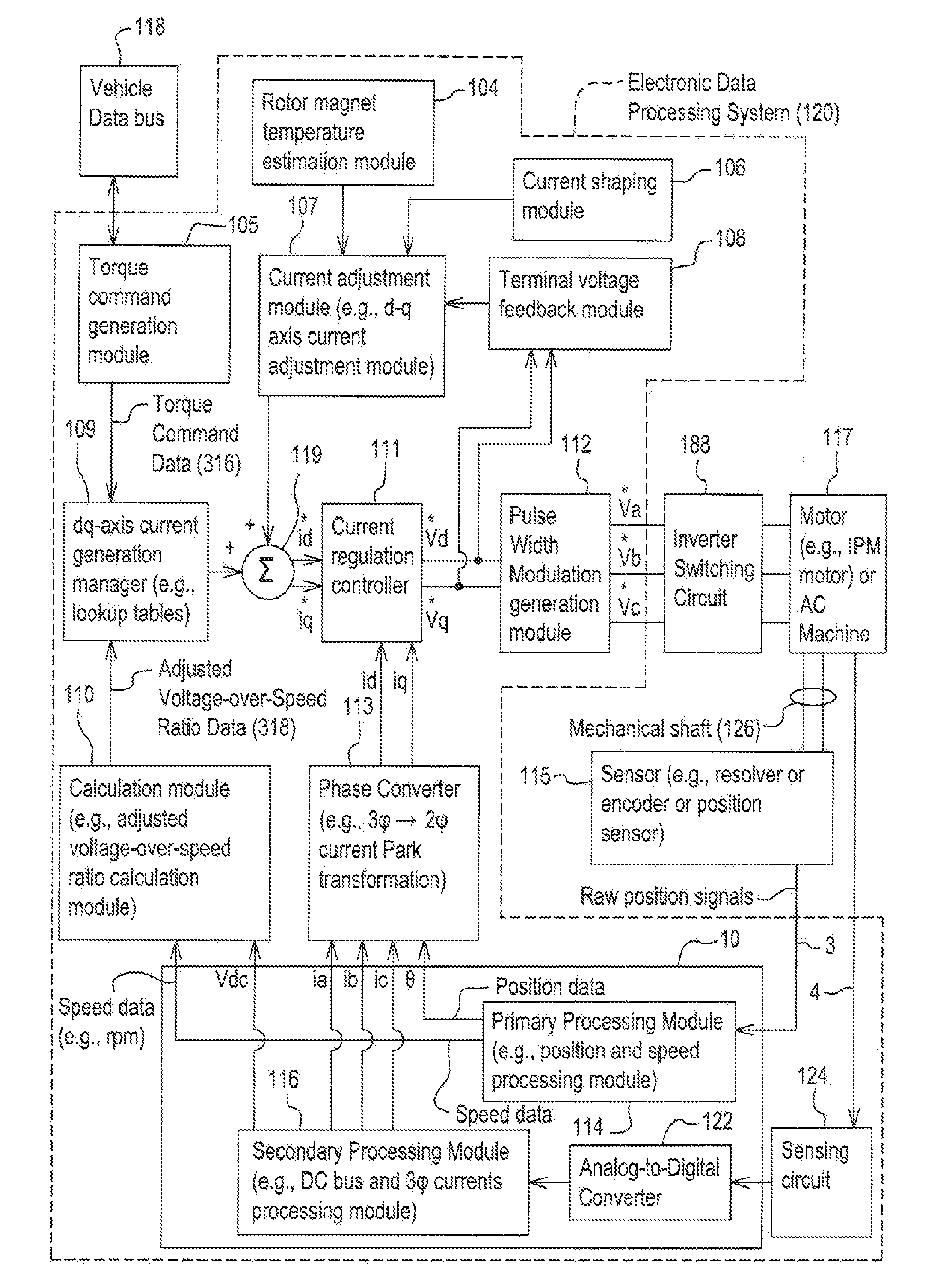
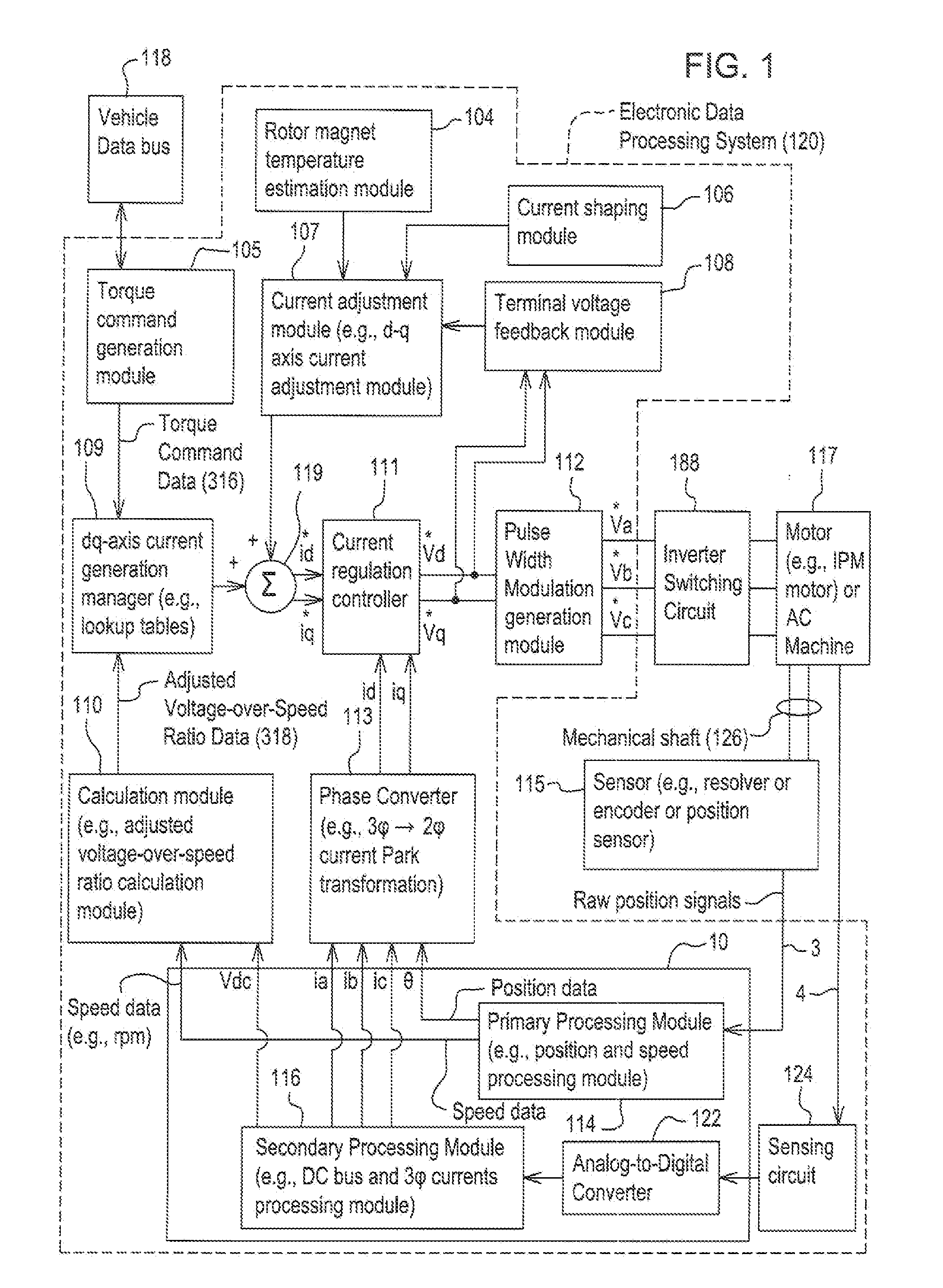
[0010]In accordance with one embodiment of the present invention, FIG. 1 discloses system for controlling a motor 117 (e.g., an interior permanent magnet (IPM) motor) or another alternating current (AC) machine. In one embodiment, the system, aside from the motor 117, may be referred to as an inverter or a motor controller.

[0011]The system comprises electronic modules, software modules, or both. In one embodiment, the motor controller comprises an electronic data processing system 120 to support storing, processing or execution of software instructions of one or more software modules. The electronic data processing system 120 is indicated by the dashed lines in FIG. 1. The present invention utilizes one or more Field Programmable Gate Arrays (FPGA) 10 for performing some of the functions of the electronic data processing system 120, and is shown in solid line in FIG. 1

[0012]The data processing system 120 is coupled to an inverter circuit 188. The inverter circuit 188 comprises a sem...


PUM


Abstract

A system and method for controlling an alternating current (AC) motor using a Field Programmable Gate Array (FPGA) to read the current and position measurements in an the AC motor, perform digital filtering of the position and current data, provide very precise synchronization of the measured phase current and position data, and output the data to a phase converter for control of the AC motor.

Description

[0001]This document claims priority based on U.S. provisional application Ser. No. 61 / 446,557, filed on 25 Feb., 2011, entitled SYNCHRONIZATION OF POSITION AND CURRENT MEASUREMENTS IN AN ELECTRIC MOTOR CONTROL APPLICATION USING A FPGA, UNDER 35 U.S.C. 119(e).FIELD OF THE DISCLOSURE[0002]The present disclosure relates to an invention that uses a Field Programmable Gate Array (FPGA) or other type of configurable digital logic to read the current and position measurements in an electric motor, perform digital filtering, and allow for very precise synchronization of measured phase current and position for motor control. It also allows for filter modifications to occur while in operation, allowing for filter properties to change based on machine electrical frequency or pulse-width modulation (PWM) frequency.BACKGROUND OF THE DISCLOSURE[0003]AC electric motor vector control requires computationally intensive algorithms; this coupled with closed loop control and precise Pulse Width Modulat...

Claims


Application Information

Patent Timeline
Patent Type & Authority Applications(United States)
IPC IPC(8): H02P6/16H02P21/00
CPCH02P21/04
Inventor WU, LONGTREMEL, CHRISTOPHER J.WANNER, KENT D.
Owner DEERE & CO
Why Eureka
Try Eureka