
System and method for road surface defects detection

a technology of defect detection and system, applied in the field of system and method for road surface defect detection, can solve the problems of missing detection or error measurement that fails to meet the requirements, unable to provide visual image for the detected object or provide the infrared thermal image that reflects the structural characteristics of the detected object, and unable to improve the existing maintenance technique.

Inactive Publication Date: 2012-08-30
GUANGZHOU SAT INFRARED TECH
View PDF10 Cites 64 Cited by
  • Summary
  • Abstract
  • Description
  • Claims
  • Application Information

AI Technical Summary

Benefits of technology

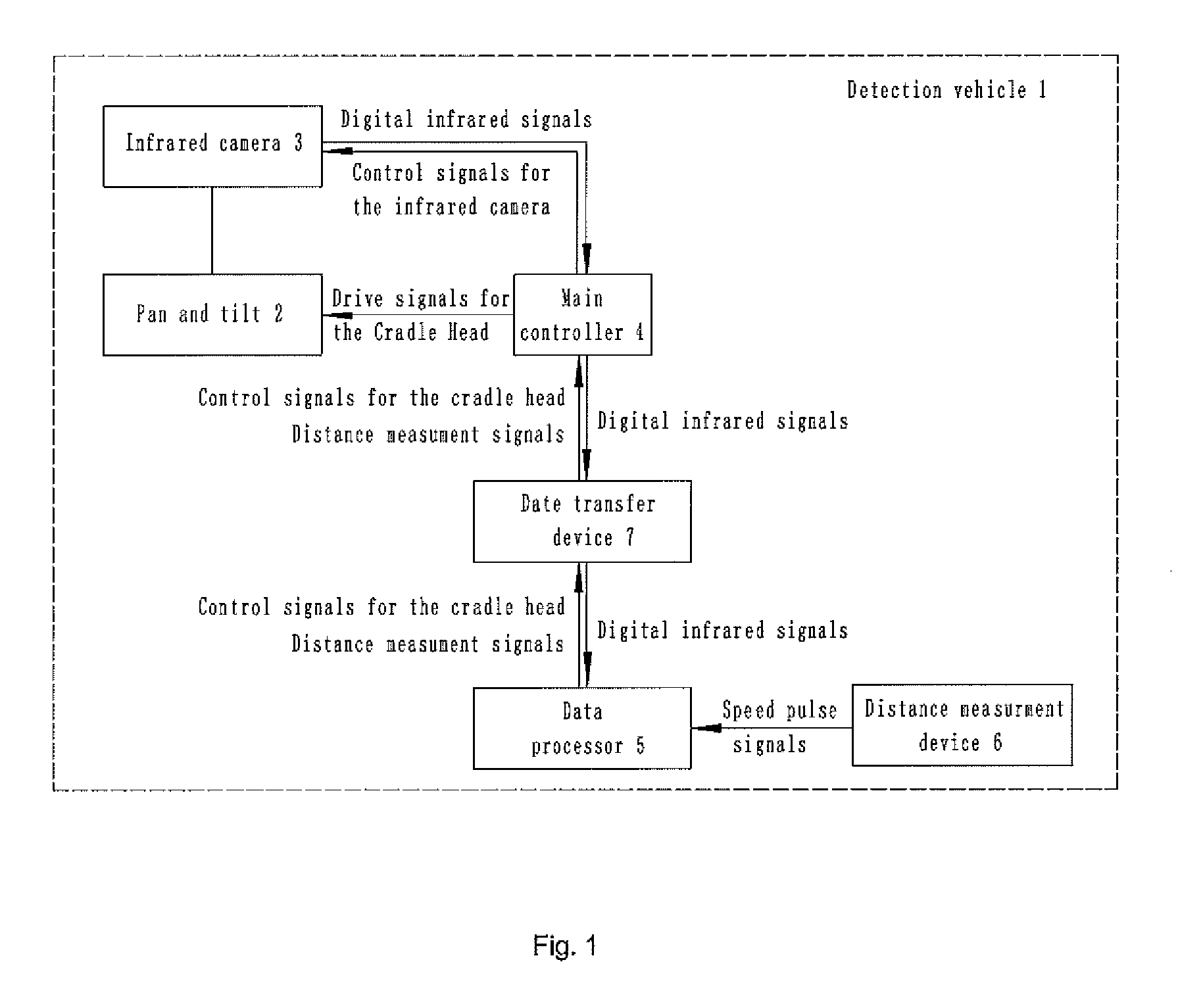
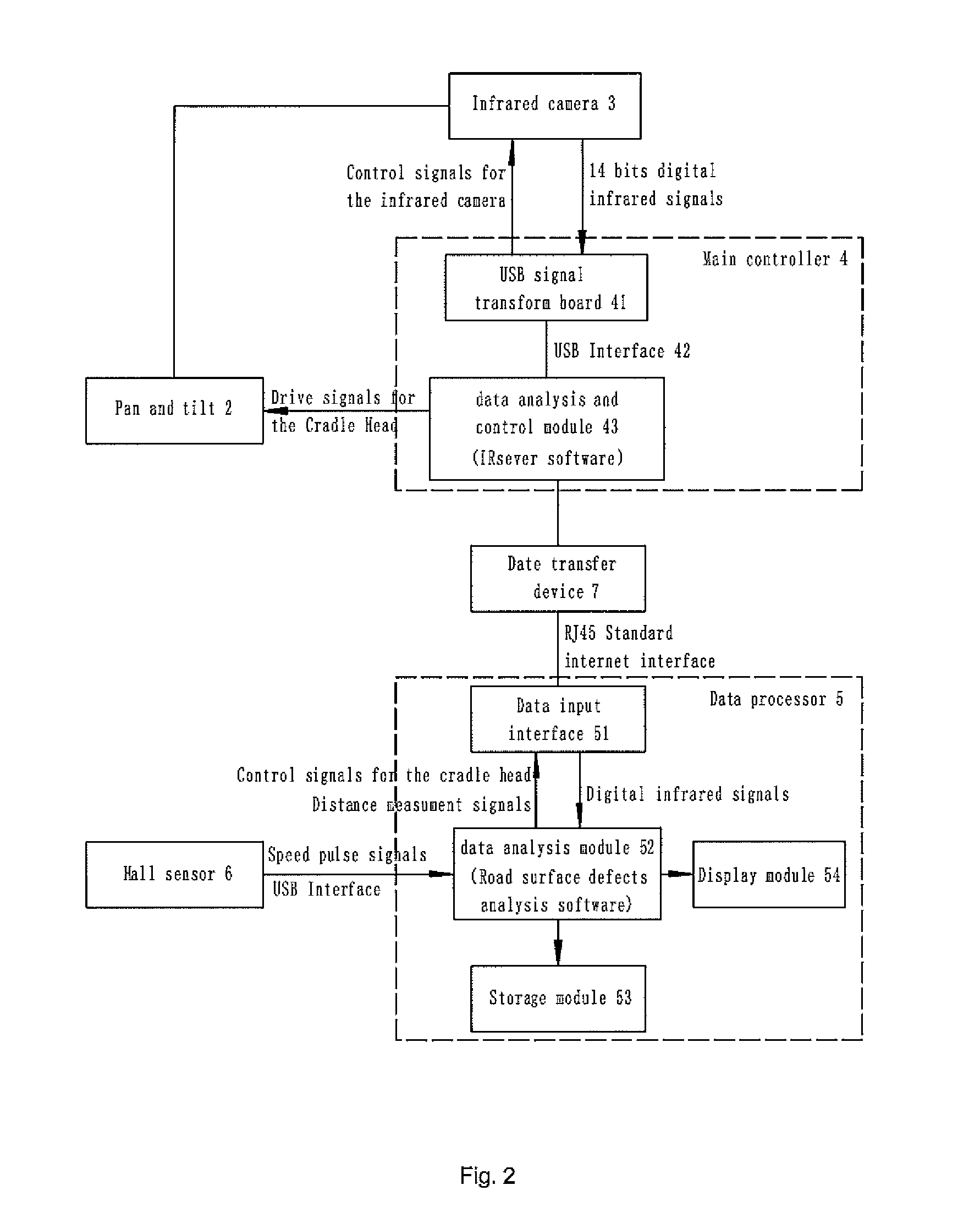
[0027]S6) the data processor using road surface defect analysis software to carry out image interception process and data analysis to the digital infrared signals, to provide successive temperature distribution graphs for the detected road surface, and to obtain the temperature trending analysis curves to accurately reflect the capture timing for the detected road surface and the corresponding temperature of each spot thereof; and
[0035]The technical solution of the present application has following beneficial effects:
[0036]①, In conjunction of the information collection technology such as infrared thermal imaging and the image digital infrared signal processing technology and the like, it's able to accomplish the rapid detection on road surface of the bituminous highway by using non-contact image captures. The system has excellent operation flexibility, clearly captured infrared images, and suffers no influence from bad weather conditions such as cloudy, rainy and foggy. Also, one single frame of image is captured only in 7 ms. As it's the thermal imaging detection, the details of the defects being captured can be shown more clearly, thus to determine on the defects more directly.
[0038]③, The digital infrared signals are analyzed, processed and managed to generate an analysis report, thus it's able to discover hidden defects in the road surface in time, which improves the existing maintenance techniques for bituminous highway.

Problems solved by technology

Moreover, although the infrared thermometer can tell temperatures on some spots (or areas) of the detected objects through one or more measurements, the detected objects can hardly provide a visual image for the detected object or provide the infrared thermal image that reflects the structural characteristics of the detected object.
Thus the existing method for road defects detection based on the infrared thermometer, since there is no real scene images available as references, obtains its detection results not quite intuitionistic, thus resulting in difficult determination, location and analysis on the road's defects, which is very likely to cause miss detections or error measurements that fail to meet the requirements in actual monitoring and evaluating.
Since this system uses the infrared thermometer as its core detecting device, and its working principle determines that it can be only used to detect temperatures but not to form images, thus it can not directly reflect the thermal distribution image of the detected object; and because the digital infrared signals measured by the infrared thermometer is an average temperature of a certain area (measured area) which is in proportional with the measurement distance, so the results of the temperature measurement may show up certain errors in accuracy; furthermore, since the measured temperature data of the infrared thermometer is a kind of dotted data (no more than an digital infrared signal of a small area, and in considering of the accuracy of road measurement, this area is supposed not too big), so the detected area of a single infrared thermometer is very limited.
Even if there are pluralities of infrared thermometers to be additionally mounted on the detection vehicle, only one lane can be monitored once at a time, so it is certainly difficult and time-consuming to thoroughly measure all lanes in a multi-lane road.

Method used


Image

  • System and method for road surface defects detection
  • System and method for road surface defects detection
  • System and method for road surface defects detection

Examples


Embodiment Construction

[0066]The foregoing and other objects, aspects and advantages of the present invention will become more apparent from the following detailed description of the present application when taken in conjunction with the preferred embodiments and accompanying drawings. The embodiments here are only used to illustrate but not to limit the present application.

[0067]Along with rapid developments of the highway and ceaseless increase of the built highway miles, it is paid more and more attention to the structural type selection, and the control to the construction technology and the construction quality is more and more strict, but some road sections may come forth damages such as water seepage, cracks, notches, wheel rut net crack, slurry jams, bridge floor break and so on after one or two year's traffic transport, which not only greatly reduce the highway's safety, fast, and comfortable traveling functions for usage, but also increase the cost of road maintenance.

[0068]In general, the damag...


PUM


Abstract

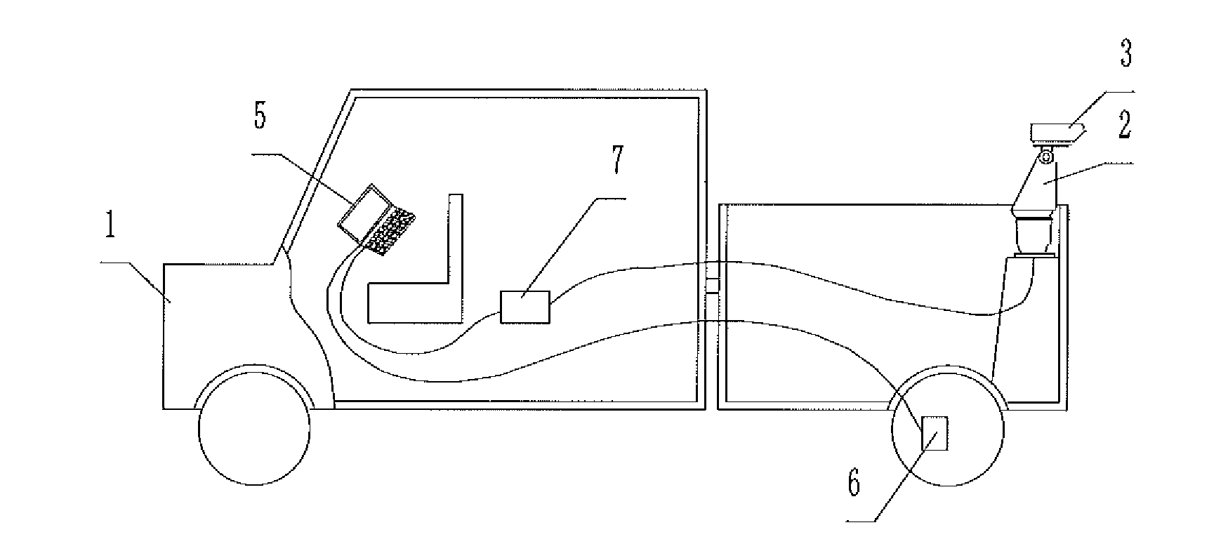
A system and method for road surface defects detection based on infrared imaging technology, while the system comprising: a detection vehicle traveling on a detected road surface; a pan and tilt provided on the detection vehicle and rotate horizontally and vertically with respect to the detection vehicle; an infrared camera detachably set on the pan and tilt, which is used to capture infrared thermal images of the detected road surface, and to output inferred thermal image digital signals about the inferred thermal images including temperature values of the detected road surface; a main controller provided on the detection vehicle and connected to the pan and tilt and the infrared camera respectively, which is used to control capture actions of the infrared camera, to control angles of the horizontal and vertical rotations of the pan and tilt, and to transform the infrared thermal image digital signals output from the infrared camera into digital signals to be used in standard network transmission; and a data processor, used to receive the digital infrared signals to be analyzed and processed to determine the type and location of defects on the detected road surface. The system of the present application has excellent operation flexibility and is able to visually display details of the defects.

Description

[0001]The present application claims the benefit of foreign priority under 35 U.S.C. 119 based upon Chinese Application 201110048227.X, filed on Feb. 25, 2011, the whole of which is hereby incorporated by reference.FIELD OF THE INVENTION[0002]The present invention relates to a system and method for road surface defects detection, especially to a system and method for monitoring the construction quality of the road surface of the bituminous highway and the like.BACKGROUND[0003]Conventionally, in China and as well in foreign countries, when monitoring on the surface defects of the bituminous highway and the like, people often use “artificial visual test method” or “evaluation and supporting maintenance technology for water seepage (dank) of the road surface based on infrared thermal differences” to make rapid detection and evaluation on defects on the road surface.[0004]The core device used by the “evaluation and supporting maintenance technology for water seepage of the road surface ...

Claims


Application Information

Patent Timeline
Patent Type & Authority Applications(United States)
IPC IPC(8): H04N5/33H04N7/18
CPCG01N33/42G01N25/72
Inventor WU, JIPINGLI, YUANIAN
Owner GUANGZHOU SAT INFRARED TECH
Learn More