Bearing carrier with multiple lubrication slots

a technology of bearing carrier and lubrication slot, which is applied in the direction of bearing unit rigid support, liquid fuel engine, machines/engines, etc., can solve the problems of needing disassembly or other maintenance-intensive actions, and achieve the effect of reducing lubricant delivery and increasing maintenance tim

Active Publication Date: 2012-08-30
FLOWSERVE MANAGEMENT CO
View PDF2 Cites 6 Cited by
  • Summary
  • Abstract
  • Description
  • Claims
  • Application Information

AI Technical Summary

Benefits of technology

[0007]According to yet another aspect of the present invention, a method of lubricating a pump bearing compartment is disclosed. The method includes introducing a lubricant to one or more bearings in the bearing compartment, the introducing taking place through a bearing assembly that includes a bearing housing configured to support the bearing, and bearing carrier that is rotatably engageable with the bearing housing. A connection formed in the housing cooperates with a channel formed in the bearing carrier such that numerous lubricant passages formed in the channel receive the lubricant from the connection through the channel regardless of a relative rotational alignment between the bearing housing and the bearing carrier. This is important in that periodic adjustments to pump impeller spacings—as well as uncertain rotational positions between the housing and carrier in the assembly—do not contribute to either (a) a reduction in lubricant delivery due to lubricant flowpath misalingment or (b) increased maintenance time needed to ensure proper alignment of the carrier and housing.

Problems solved by technology

In this way, periodic adjustments made to (for example) the pump's impeller to control a gap or related spacing between it and a portion of the flowpath into which the impeller is disposed will not necessitate disassembly or other maintenance-intensive actions to ensure continued lubricant delivery to the bearings contained within the assembly.

Method used


Image

  • Bearing carrier with multiple lubrication slots
  • Bearing carrier with multiple lubrication slots
  • Bearing carrier with multiple lubrication slots

Examples


Embodiment Construction

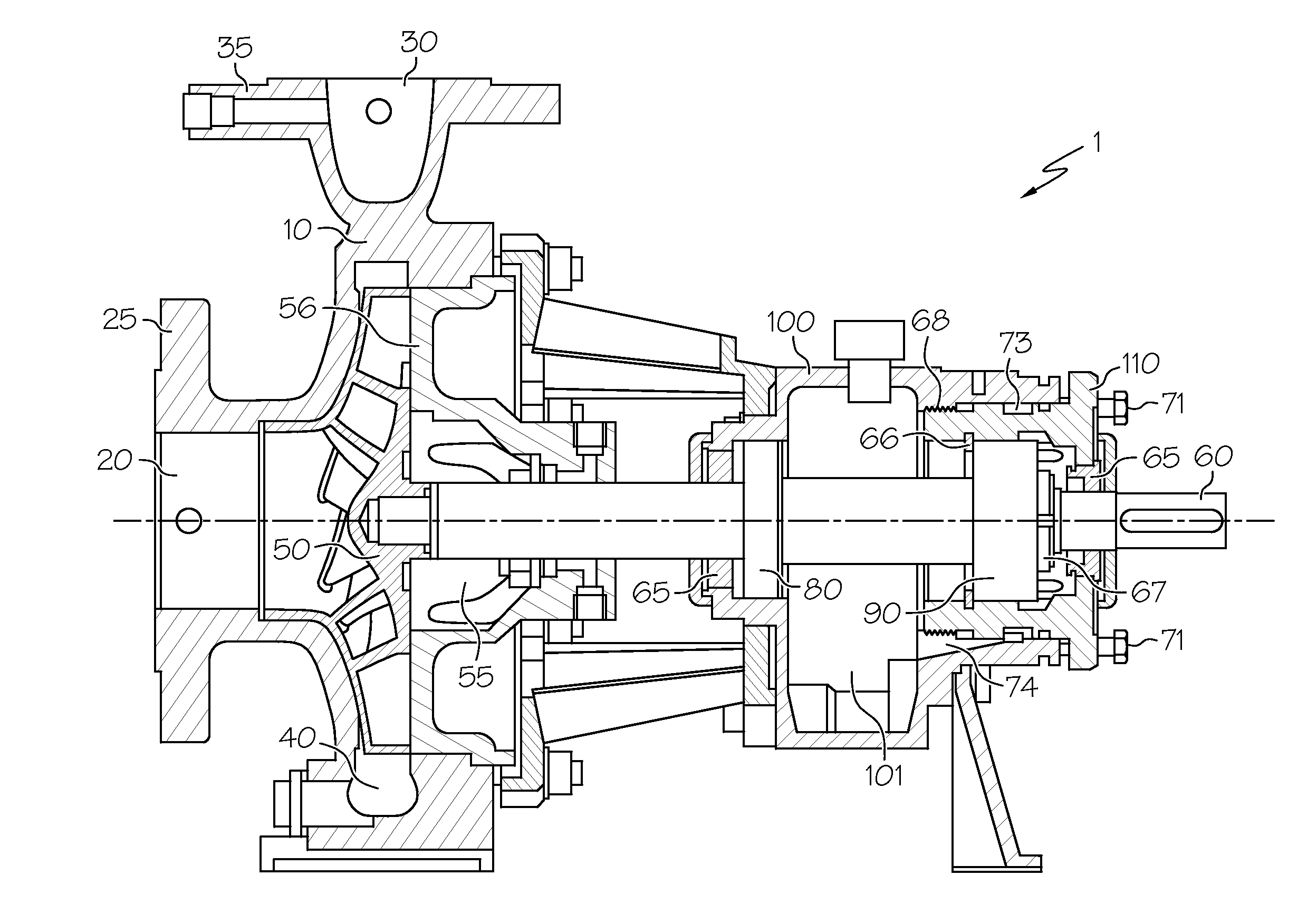
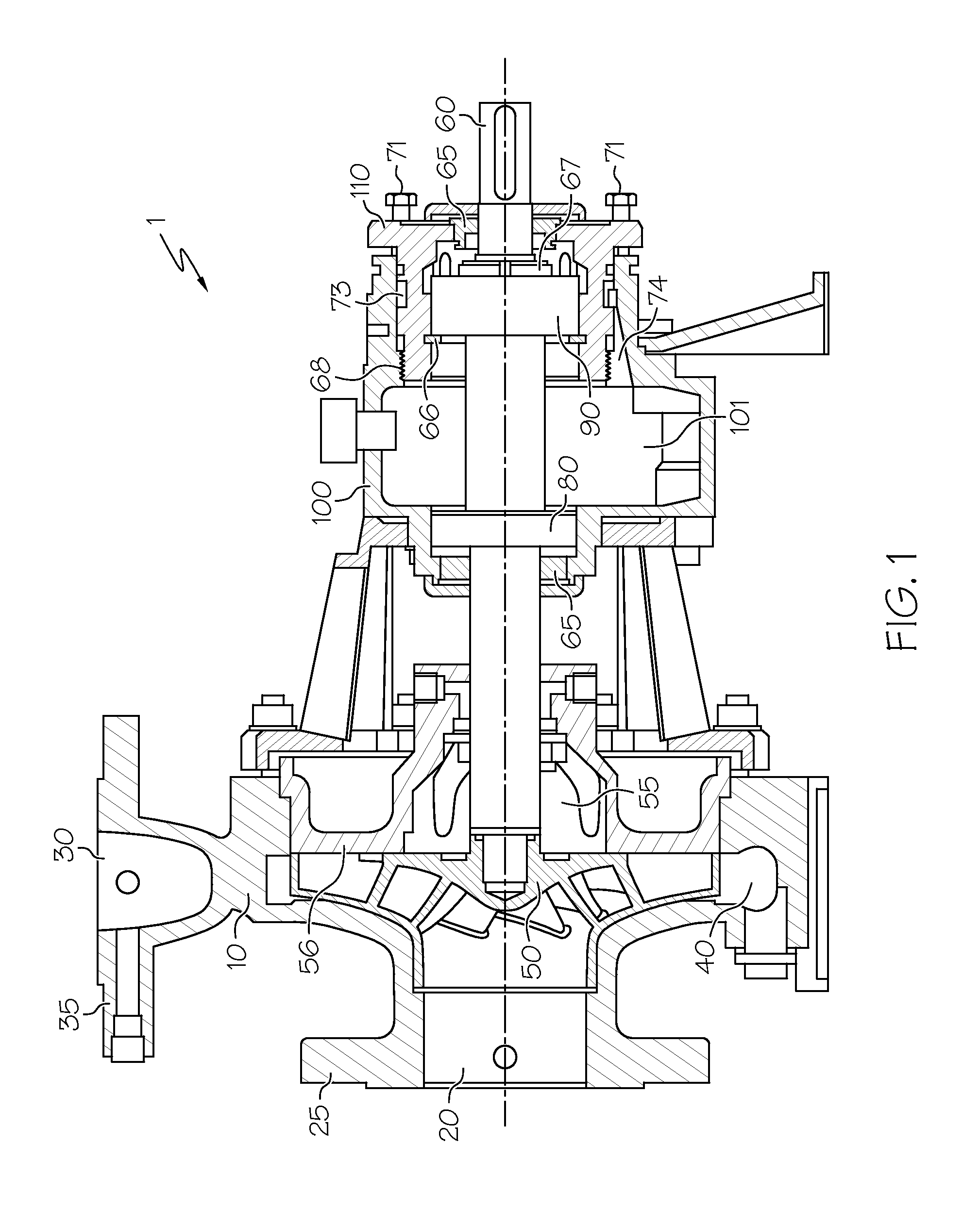
[0013]Referring first to FIG. 1, a cutaway view of a centrifugal pump 1 according to the present invention is shown. Pump 1 includes a pump housing (or casing) 10, inlet 20 and outlet 30 along with a fluid flowpath (or pumping chamber) 40 defined between them. In the present context, while pump housing 10 may be associated predominantly with the casing formed around the inlet 20, outlet 30 and flowpath 40, as well as defining integral or connectable footers and other structural hardware, it will be understood that additional covers, casing or related containment structure may also be included. Inlet flange 25 and outlet flange 35 form mounting locations to fluidly connect the respective inlet 20 and outlet 30 of pump housing 10 to corresponding conduit (not shown), and may include apertures formed therein to receive screws, bolts or related fasteners that can be used to facilitate such connection. An impeller 50 is mounted to an axle or shaft 60 that is rotated by the operation of a...


PUM


Abstract

A bearing assembly, a pump with a bearing assembly and a method of lubricating a pump bearing using a bearing assembly. The bearing assembly includes a bearing carrier and a bearing housing that are rotatably connected to one another to permit axial adjustment of the pump's impeller or other fluid-conveying apparatus, as well as variable rotational positioning of the bearing carrier relative to a pump housing. Numerous lubricant access apertures placed around the periphery of the bearing carrier facilitate lubricant passage from a connection on the bearing housing to the bearings, regardless of the rotational position of the carrier relative to the bearing housing or other pump structure.

Description

[0001]This application claims the benefit of the filing date of U.S. Provisional Application No. 61 / 446,731, filed Feb. 25, 2011.BACKGROUND OF THE INVENTION[0002]The present invention relates generally to pumps, and more particularly to a bearing carrier for such pumps that use multiple lubrication access locations for bearings located within the pump.[0003]Chemical process pumps are often used to move petroleum products, industrial chemicals, solvents and related fluids. Such pumps are especially well-suited for use with low-viscosity and relatively non-abrasive fluids. In one particular form, chemical process pumps employ rotating vanes that are placed relative to complementary stator or related housing surfaces to ensure tight tolerances and precise degrees of adjustment. One form of such pump, which is manufactured by the assignee of the present invention, is a centrifugal pump with a rotating impeller; such pump is referred to commercially as the Flowserve Durco® Mark 3™ ISO Pu...

Claims


Application Information

Patent Timeline
Patent Type & Authority Applications(United States)
IPC IPC(8): F04D29/046F16C33/66F16C19/30F04D29/00
CPCF04D29/0462F04D29/061F04D29/622F16C2226/60F16C33/6622F16C35/077F16C2360/42F16C23/06
Inventor RILEY, PHILIP RICHARDATAYILVEETIL, SARATHBOWER, JOHN ROGER
Owner FLOWSERVE MANAGEMENT CO
Why Eureka
Try Eureka