Mechanical module for horsepower amplification

Inactive Publication Date: 2012-09-06
ZAMBRANA LUIS ANTONIO
View PDF0 Cites 3 Cited by
  • Summary
  • Abstract
  • Description
  • Claims
  • Application Information

AI Technical Summary

Problems solved by technology

Present limitations inherent to horsepower producing mechanisms are causing the actual motorized equipment manufactures to adventure in

Method used


Image

  • Mechanical module for horsepower amplification
  • Mechanical module for horsepower amplification
  • Mechanical module for horsepower amplification

Examples


first embodiment

—FIGS. 1, 2, 2A-2H, 3, and 3A—First Embodiment

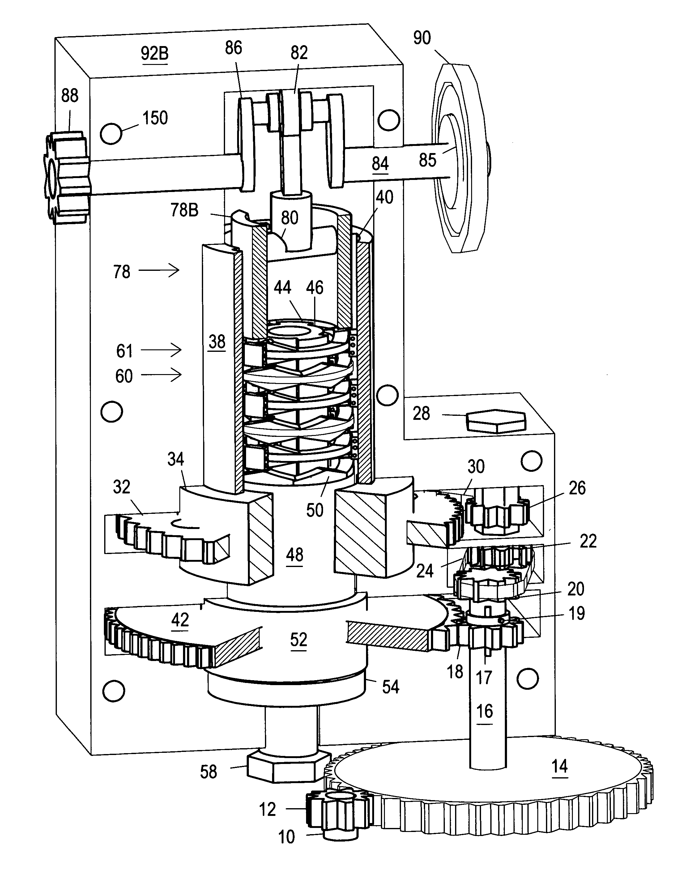
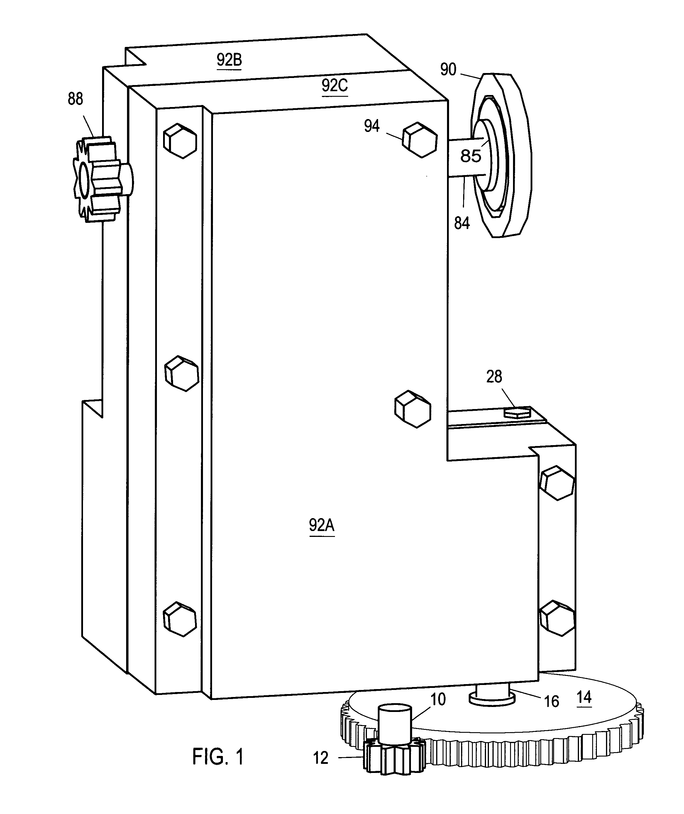
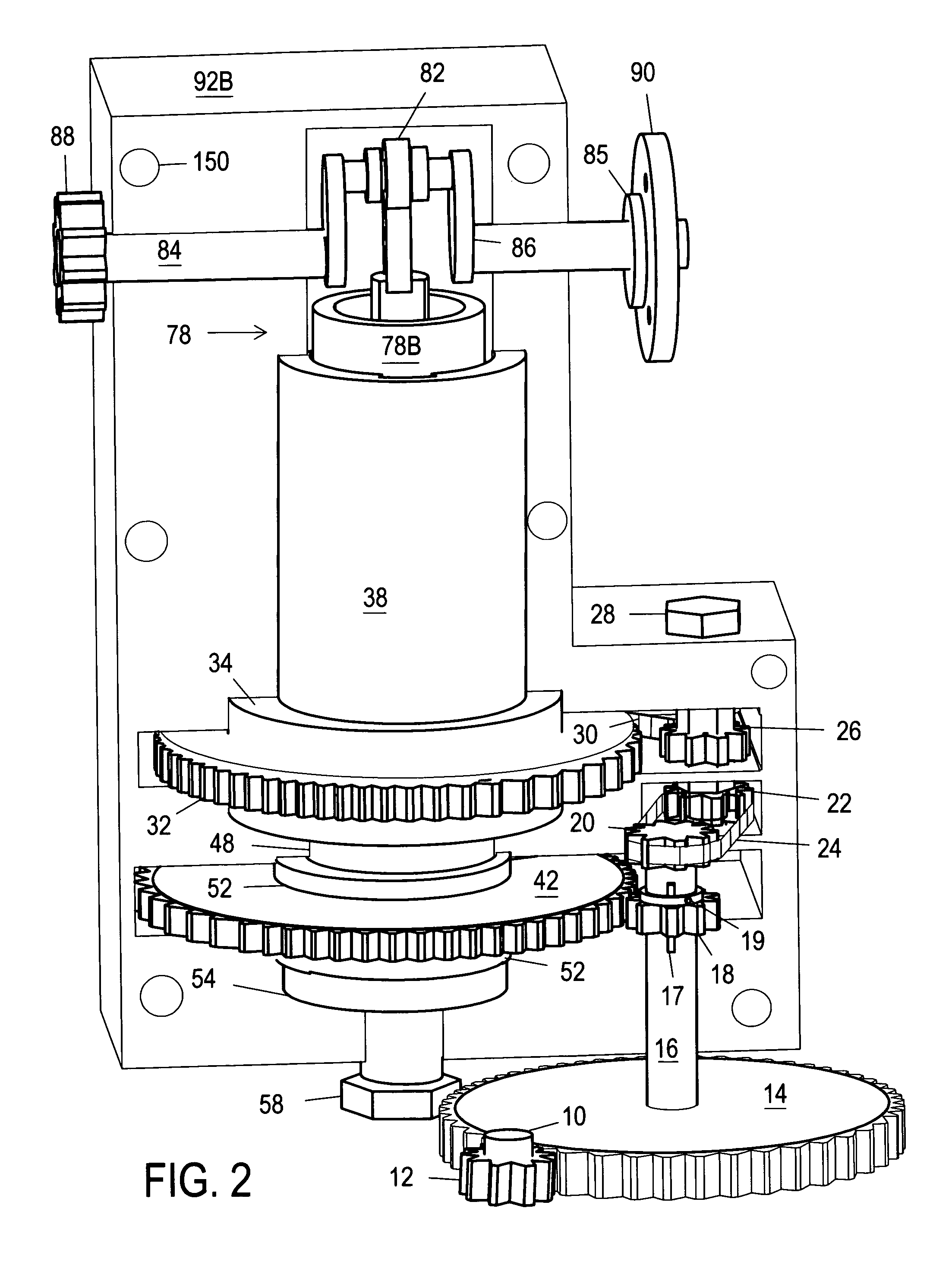
[0024]FIG. 1 (front perspective view) shows an overall view of the horsepower amplifier of the first embodiment. The horsepower amplifier is a mechanical device designed to multiply the magnitude of any rotational force applied to input gear / wheel 14. Rotating assemblies and a preselected number of gears mounted on frame / housing 92A are connected to gear 14 to create a more powerful directional force upon activation. The magnitude of the original input force (TORQUE) and the rate of rotation (RPM) are significantly increased. The reliability of current electric or fuel driven horsepower sources is potentially increased to satisfy current needs.

[0025]Frame 92A is a two halves housing. Bolts 94 are torqued to threading 150 to support halves 92B and 92C after a gasket or seal (not shown) is installed on mating surfaces to prevent oil or fluids leakage. Bearings (not shown) are installed where inner components depend on housing 92A for suppo...

second embodiment — fig 4

Description and Operation—Second Embodiment—FIG 4

[0052]FIG. 4 is a front perspective view of a second embodiment of the horsepower multiplier module. A portion of cylindrical support 38 and frame 34 are removed to fully disclose CPRs mounted on respective assemblies and to show chain 118 routing. A single horsepower multiplier module is mounted to casing 116 (partially shown in three pieces) to provide a better view and understanding the full operation of the second embodiment. Two or more modules are connected to ensure continous force is acting on shaft 84 to pull chain 118 and all CPRs back.

[0053]Mounting frame or casing 116 is modified to allow the mounting of sprocket gear 120 if necessary to follow the location of arms 86. Shaft 84 is mounted on a different location in relation to first embodiment and can be mounted at any angle to provide more flexibility when output coupling device 90 or gear 88 are connected to application. Shaft 16 replaces bolt 28 as shown in FIG. 4. All ...


PUM


Abstract

One embodiment of the horsepower amplifier module (FIG. 2) proofs the usefulness of a new approach to mechanical interventions. Mechanical advantage principles and the laws of leverage are fully exploited to increase energy efficiency while operating any horsepower producing means. Newly designed pressure ring (60), and pressure ring (61), are mounted respectably on rotary assemblies (FIG. 2B) and (FIG. 2C). Rotational energy applied to assemblies prompts the lateral displacement of components (60) and (61). A more powerful force is created and is directed to collector (78). Multiple modules supplying energy to same shaft (as shown in FIG. 3) offer a variety of options for effective operation of adopted application. A second embodiment (FIG. 4) is described as a possible arrangement available to enhance the overall capabilities of the horsepower multiplier module.

Description

CROSS-REFERENCE TO RELATED APPLICATIONS[0001]This application claims the benefit of provisional patent application Ser. No. 61 / 464,464, filed 2011 Mar. 4 by the present inventor.FEDERALLY SPONSORED RESEARCH[0002]Not ApplicableSEQUENCE LISTING OR PROGRAM[0003]Not ApplicableBACKGROUND[0004]1. Field[0005]This invention generally relates to mechanical devices, specifically a horsepower multiplier module for energy conservation.[0006]2. Prior Art[0007]Present limitations inherent to horsepower producing mechanisms are causing the actual motorized equipment manufactures to adventure into fruitless new alternatives. The high cost of research and testing seldom satisfies expectations in performance and / or financial gain. Increasing the output capacity of such machines in a cost effective manner creates numerous opportunities directly and indirectly to all industries depending on horsepower technologies to sustain daily operations. My module greatly increases the reliability of any horsepowe...

Claims


Application Information

Patent Timeline
IPC IPC(8): F16H25/12
CPCF03G7/10Y10T74/18304F16H25/125
Inventor ZAMBRANA, LUIS ANTONIO
Owner ZAMBRANA LUIS ANTONIO
Why Eureka
Try Eureka