Laser-Optical Position Detecting Module

Active Publication Date: 2012-09-06
NATIONAL TSING HUA UNIVERSITY
View PDF2 Cites 8 Cited by
  • Summary
  • Abstract
  • Description
  • Claims
  • Application Information

AI Technical Summary

Benefits of technology

[0009]The primary objective of the present invention is to provide a laser-optical position detecting module, in which, laser beam is used as light source, and a phase retarder and a passive optical device used for reflecting the laser beam

Problems solved by technology

Although the phenomenon of the reducing of the overall light brightness of the display panel 110 can be solved by increasing the quantity of the LED light source 110, such way increases the power consumption on the contrary.
However, because the laser has the high directivity characteristics, it must

Method used


Image

  • Laser-Optical Position Detecting Module
  • Laser-Optical Position Detecting Module
  • Laser-Optical Position Detecting Module

Examples


Embodiment Construction

[0025]To more clearly describe a laser-optical position detecting module according to the present invention, embodiments of the present invention will be described in detail with reference to the attached drawings hereinafter.

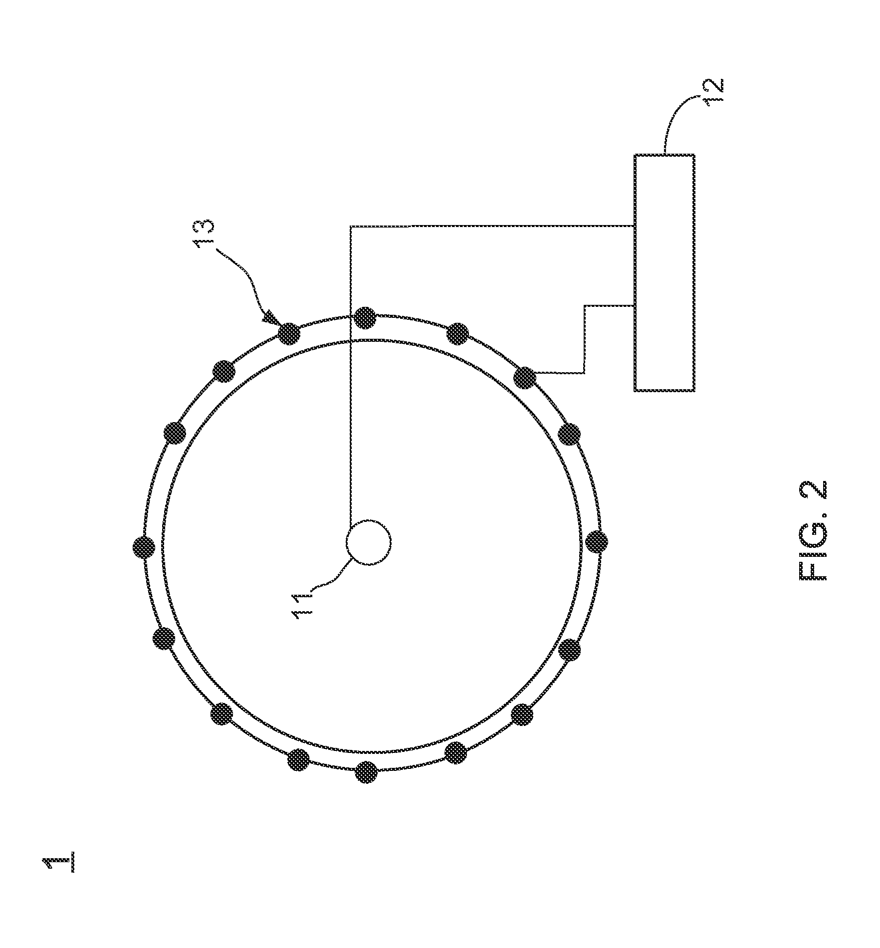
[0026]Please refer to FIG. 2, which illustrates a framework diagram of a laser-optical position detecting module according to the present invention. As shown in FIG. 2, the laser-optical position detecting module includes: a laser mode conversing assembly 11, adopted for emitting a modulated laser beam and expending the modulated laser beam to a two-dimensional detecting plane; a drive control unit 12, connected to the laser mode conversing assembly 11 for driving the laser mode conversing assembly 11 to emit the modulated laser beam; and a light-detecting array 13, disposed around the two-dimensional detecting plane for detecting the modulated laser beam. Wherein when an object is located on the two-dimensional detecting plane, the partial modulated laser beam...


PUM


Abstract

The present invention relates to a laser-optical position detecting module with a laser light source, comprising: laser mode conversing assembly, having a laser source capable of emitting a time-modulated laser beam; a laser mode conversing unit, used to expand the time-modulated laser beam to a two-dimension sensing plane; a drive control unit, adopted for driving the laser source to emit the time-modulated laser beam; and a detector matrix, used for detecting the. The laser mode conversing unit has a phase delay device and a passive optical device capable of reflecting the light; so that, through the laser mode conversing unit, the laser-optical position detecting module can expand the light emitted by the laser source to the two-dimension sensing plane without using any other mechanical scanning; moreover, it make the energy of the light emitted by the laser source not easily decays, so as to maintain the accuracy of light detection.

Description

BACKGROUND OF THE INVENTION [0001]1. Technical Field[0002]The present invention relates to an optical position detecting device, and more particularly, to a laser-optical position detecting module capable of expanding laser beam to a two-dimensional plane without using mechanical scanning.[0003]2. Description of Related Art[0004]With the development of the computer technology, electronic products having touch screens are continuously introduced new in recent, wherein the touch screen provides user to directly touch and control the figures shown in the screen by using an object or fingers. After the user touch and control the figures shown in the screen by using the object or the fingers, a feedback system in the electronic product would drive various hardware and firmware according to the pre-programmed program, so as to show vivid vided effects in the screen. Commonly, the touch screens can be divided into the following types of: resistive touch screen, capacitive touch screen, sur...

Claims


Application Information

Patent Timeline
IPC IPC(8): G01B11/14
CPCG06F3/0421
Inventor LIN, YEN-YINLIN, YUAN-YAOZHU, SHI-WEICHIANG, AN-CHUNGLEE, MANG-SHIANGWU, CHING-HUEI
Owner NATIONAL TSING HUA UNIVERSITY
Why Eureka
Try Eureka