Method of fabricating electronic cards including at least one printed pattern

a technology of electronic cards and printed patterns, which is applied in the association of printed circuit non-printed electric components, instruments, printing, etc., can solve the problems of not being able to use for making patterns in different colours or that completely cover a certain surface of the card, and the method of writing a text or a pattern is limited, etc., to achieve good support, high definition print, and smoke-free

Inactive Publication Date: 2012-09-06
NAGRAID SECURITY
View PDF1 Cites 1 Cited by
  • Summary
  • Abstract
  • Description
  • Claims
  • Application Information

AI Technical Summary

Benefits of technology

[0053]Another interesting advantage of the invention will also be noted: In order to allow plastic layers to be properly laminated, those skilled in the art preferably choose layers with matt surfaces, i.e. with a micro relief. Thus, in the method of the prior art described in the introduction, printing is generally performed on such matt plastic sheets. This surface state limits the definition possible for the printed pattern. However, within the scope of the present invention, when the first pattern is printed on the thick sheet, the latter may have smoother surfaces. This thick sheet needs only to be made, at least in a final step, in a press that has smooth surfaces. The thick sheet that results from the methods according to the invention can thus be perfectly smooth and flat, which means that very fine and very small characters or patterns can be printed, i.e. a very high definition print can be obtained.
[0054]Within the scope of the improved method, the invention is very advantageous, since first of all a thick layer is fabricated, incorporating the electronic elements. As mentioned above, this thick layer may have flat, uniform surfaces. Moreover, the thick layer is stable since it has a minimum of internal residual tensions compared to the inner layers of the prior art. Thus, this thick layer forms a very good support for high definition printing by the card manufacturer or printing specialist. A thick sheet is thus obtained that incorporates the electronic elements and has, in particular, very high quality patterns on both sides, in particular at least one security pattern. In order to obtain the finished cards, all that is missing from the thick printed sheet are the transparent protective coatings. Transparent films can be printed in a relatively simple and inexpensive station, and then assembled easily with the thick sheet, particularly via a small supply of energy; which ensures that the printed patterns are not damaged during this final assembly. Printing on the transparent outlays and assembly of the outlays with the thick sheet can thus be performed using less complex and less expensive stations and by less qualified personnel. These steps can be achieved at other locations by the client with stations that belong to him.
[0055]In summary, during final lamination or bonding after printing, the fact of having only one central thick sheet, which is not deformed locally or overall in the presence of a small supply of energy, and two relatively thin outlays between which the sheet is arranged, constitutes a major advantage that guarantees fabrication of cards that have very high quality prints, which are not likely to be damaged during said lamination or final bonding. This means that industrial efficiency or yield can be increased and printing on the transparent outlays and the assembly thereof to the central thick sheet can be performed at other locations in different manufacturing sites to those where the thick sheets are made and the high quality prints are performed on the surfaces of the sheets.
[0056]The invention also concerns an intermediate or semi-finished product involved in the fabrication of cards according to the invention. This intermediate product is formed by a sheet that incorporates or embeds a plurality of electronic units and defines a respective plurality of card bodies, said sheet having on a first surface a plurality of first printed patterns.
[0057]In an advantageous variant, said plurality of first patterns is covered by a protective coating, in particular by a plastic film, a resin layer or a lacquer. It should be noted that the lacquer could be, for example, a sort of transparent ink deposited with the aid of a transfer film.
[0058]In a first case, the protective coating is temporarily arranged on the thick sheet. It is thus not very adherent to the sheet and can therefore be removed.

Problems solved by technology

This method of writing a text or a pattern is limited and requires a relatively long period of time since the laser beam has to follow a line that matches the desired pattern.
However, it cannot be used for making patterns in different colours or that entirely cover a certain surface of the card.
Since the height of inlay 2 is limited, the height of the electronic elements that can be incorporated in inlay 2 is also limited.
It will be noted that it is difficult in these conditions to obtain an inlay that has proper flat surfaces and exhibits homogeneous behaviour in the presence of heat.
Thus, as already mentioned, the conventional method used by those skilled in the art has a first drawback, due to the limited thickness of inlay 2; which limits the height of the electronic elements incorporated and generates deformations in the printed intermediate layers when they pass into the hot press used to form the finished card.
It is therefore to be noted that, in addition to the fact that it is very difficult to obtain cards with high definition printed patterns without local deterioration, fabricating these cards must be performed by a specialised manufacturer if one wishes to obtain high quality cards.
Thus, flexibility in the finish of the cards, which one might expect from the separate fabrication of inlays incorporating electronic elements and intermediate layers printed in plastic sheet printing stations, cannot be used in practice.
Consequently, it is not really possible to envisage, at least in part, performing the printing and final assembly of the cards elsewhere at a distributor's or card user's.

Method used


Image

  • Method of fabricating electronic cards including at least one printed pattern
  • Method of fabricating electronic cards including at least one printed pattern
  • Method of fabricating electronic cards including at least one printed pattern

Examples


Embodiment Construction

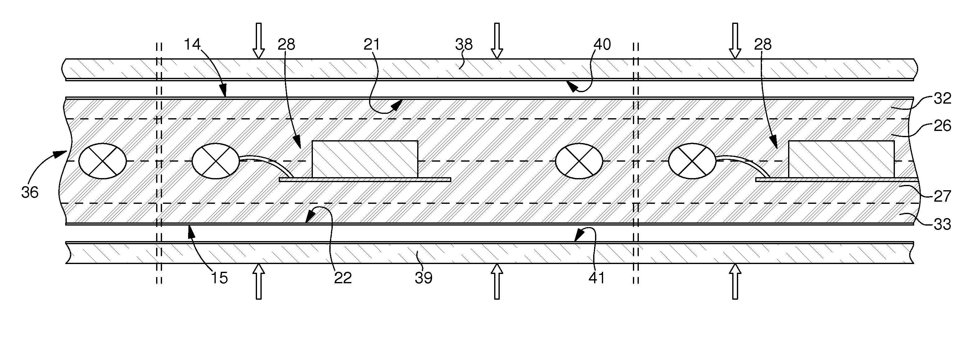
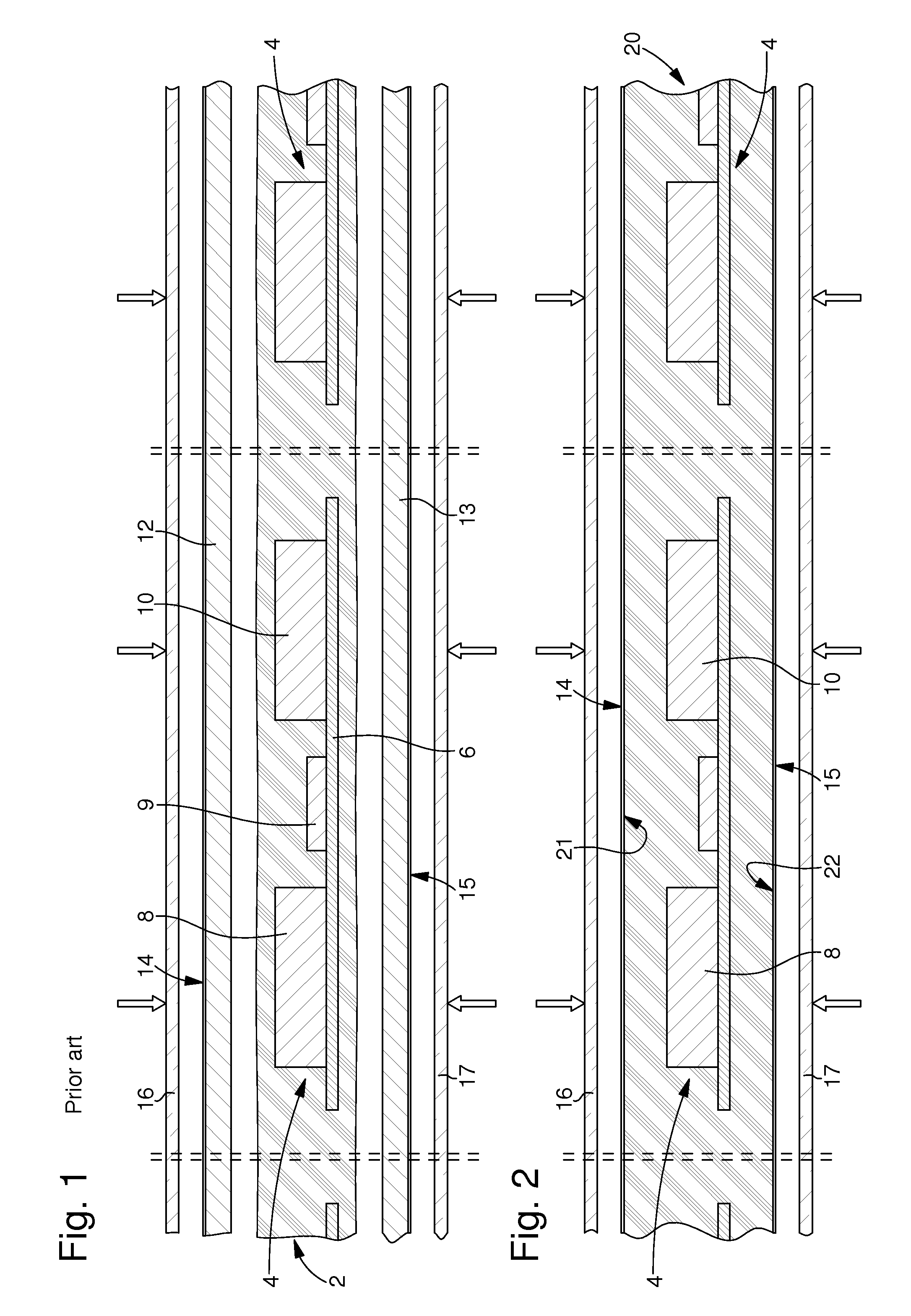
[0071]The first implementation mode of the method according to the invention show in FIG. 2 is characterized in that a thick sheet 20, which incorporates or embeds a plurality of electronic units 4, is first of all formed. This thick sheet 20 defines a plurality of card bodies each including an electronic unit 4.

[0072]The thick sheet 20 can be made by any technique known to those skilled in the art, particularly using several layers laminated or bonded to each other. In a variant, at least one central layer has apertures, which house at least electronic elements 8 and 10. In another variant, electronic unit 4 is incorporated in a press where plastic layers are first of all softened sufficiently and then pressed in a controlled manner so that electronic unit 4 penetrates these layers to form its own housing. Thick sheet 20 can, in another variant, be obtained by pouring or injecting a liquid resin.

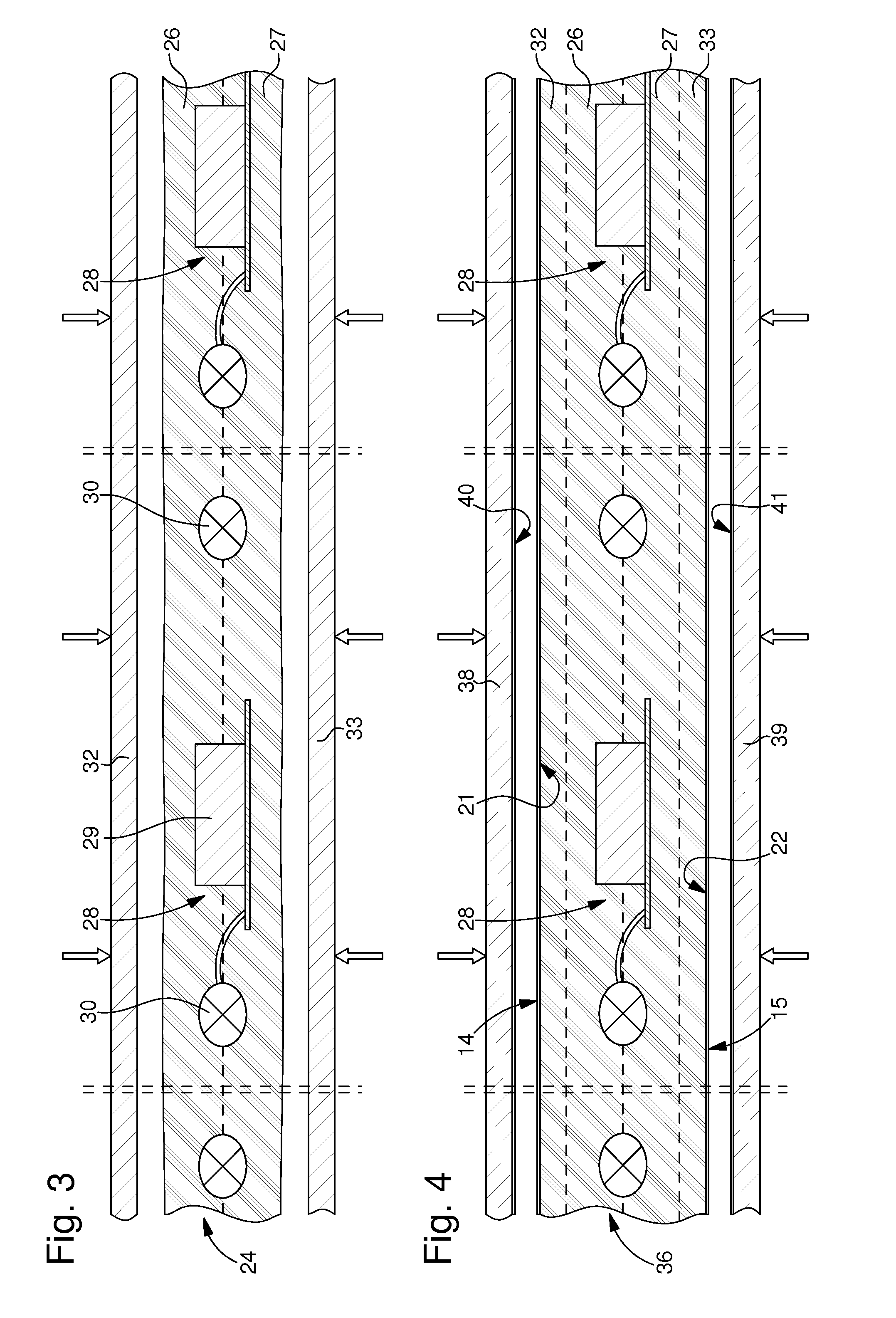
[0073]Preferably, flat surfaces 21 and 22 of thick layer 20 are opaque, and in particul...


PUM


Abstract

A method for fabricating electronic cards includes: A) forming a plurality of card bodies in the form of a thick sheet in which is respectively imbedded a plurality of electronic units or modules; B) printing a plurality of first patterns on a first face of the thick sheet in a printing station in which ink is applied on the first face for making the first patterns; and C) applying a first at least partially transparent coating on each printed first pattern, that adheres to the card body. The method also includes printing a plurality of second patterns on the inner surface of a film forming the first coating. Preferably, the printing of the first patterns is carried out in an offset type station for printing high definition patterns, essentially of the security type. The second patterns define personal data. The printed thick sheet defines an intermediate product.

Description

[0001]This is a Divisional Application of Ser. No. 12 / 526,382, filed Aug. 7, 2009, which is a National Phase Application in the United States of International Patent Application PCT / EP 2008 / 051447 filed Feb. 6, 2008, which claims priority on European Patent Application No. 07102087.9 of Aug. 7, 2007. The entire disclosures of the above patent applications are hereby incorporated by reference.FIELD OF THE INVENTION[0002]The present invention concerns the fabrication of electronic cards, i.e. cards that include at least one electronic unit and have any shape or contour. More specifically, the invention concerns the fabrication of electronic cards that have at least one printed pattern, which is protected by an at least partially transparent coating, particularly an overlay.[0003]In a particular implementation of the invention, the fabricated card has patterns printed on both of its two flat surfaces, each printed pattern being protected by an at least partially transparent overlay.[00...

Claims


Application Information

Patent Timeline
Patent Type & Authority Applications(United States)
IPC IPC(8): H05K1/14
CPCG06K19/077B42D25/45B42D25/00H05K13/0023B42D25/485H05K13/00G06K19/07718
Inventor DROZ, FRANCOIS
Owner NAGRAID SECURITY
Why Eureka
Try Eureka