Optical networks

a technology of optical networks and optical fibers, applied in the field of optical networks, can solve the problems of affecting the service life of the optical fiber, and requiring maintenan

Active Publication Date: 2012-09-06
TELEFON AB LM ERICSSON (PUBL)
View PDF4 Cites 22 Cited by
  • Summary
  • Abstract
  • Description
  • Claims
  • Application Information

AI Technical Summary

Benefits of technology

[0045]The method thereby remotely sets the wavelength of an optical transmitter in an optical network based simply on detection of the presence of the second optical signal. Setting the wavelength of an optical transmitter is thus controlled just utilizing the physical layer of the network in which the method is applied, independent of the transmission protocol, standard and bit rate used by the network. The method ensures that the optical transmitter only generates and transmits a second optical signal following detection of the first optical signal, thereby controlling power consumption of the network in which the method is applied.

Problems solved by technology

Providing each ONU with a different fixed wavelength transmitter is a costly approach and has maintenance problems associated with it.
However, using tunable lasers at the ONUs faces the problem of tuning each laser to the correct wavelength for its associated channel.

Method used


Image

  • Optical networks
  • Optical networks
  • Optical networks

Examples


first embodiment

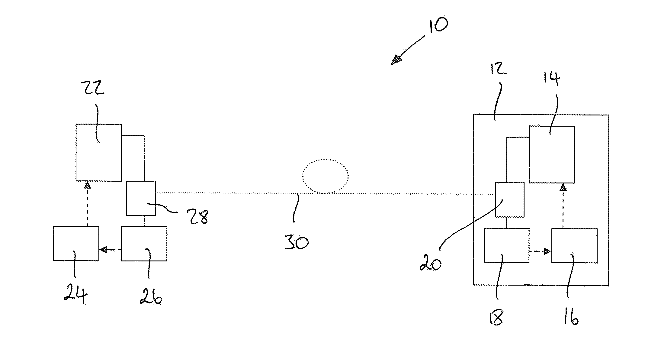
[0063]Referring to FIG. 1, the invention provides an optical network 10 comprising an optical network element 12. The optical network element 12 comprises a first optical transmitter 14, a first controller 16 and an optical receiver 18.

[0064]The optical network element 12 will typically be connected to an optical link 30, which is shown for reasons of clarity but which does not form part of this embodiment of the invention. The optical network element 12 further comprises a band-split filter 20 by which the optical link 30 is coupled to the first optical transmitter 14 and to the optical receiver 18.

[0065]The first optical transmitter 14 is arranged to generate and transmit a first optical signal. The first controller 16 is arranged to control the first optical transmitter 14 to generate and transmit the first optical signal at a wavelength selected from a pre-determined plurality of wavelengths, being the wavelengths of channels of the optical network 10. The optical receiver 18 is...

second embodiment

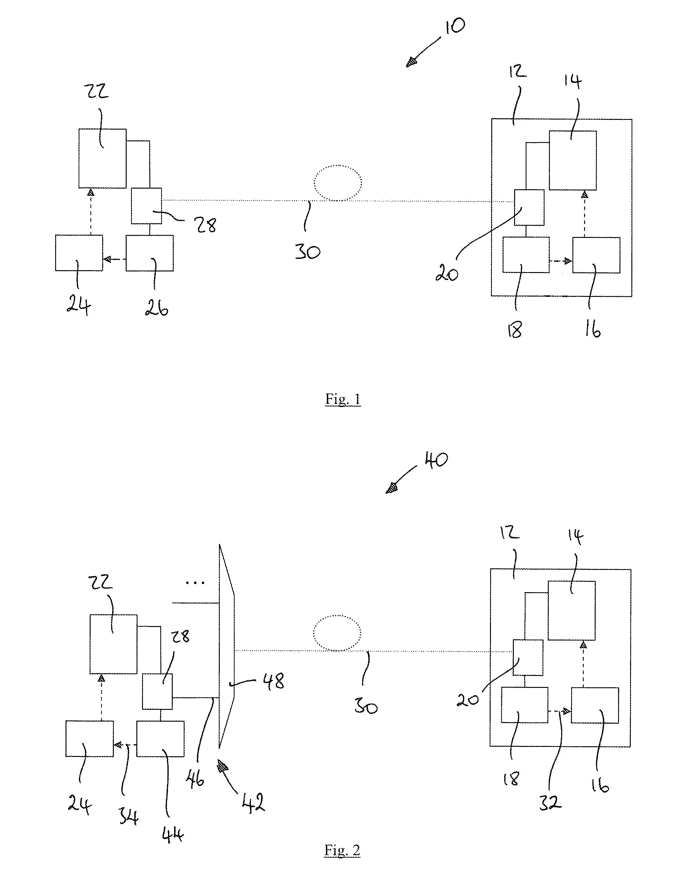
[0073]the invention, shown in FIG. 2, provides an optical network 40 which is substantially the same as the optical network 10 of the previous embodiment, with the following modifications. The same reference numbers are retained for corresponding features.

[0074]In this embodiment, the optical receiver apparatus 42 comprises an optical detector 44 coupled to an output port 46 of a wavelength selective router 48. The output port 46 is coupled to the optical detector 44 via the band-split filter 28. The wavelength selective router 48 is coupled, on its input side, to the optical link 30. As before, the optical link 30 is shown only for clarity and does not form part of this embodiment.

[0075]The first optical transmitter 14 comprises a wavelength tuneable laser and the second optical transmitter 22 comprises a fixed wavelength laser. Each of the optical receiver 18 and the optical detector 44 comprise wide band photodetectors.

[0076]In this example, the wavelength selective router 48 com...

third embodiment

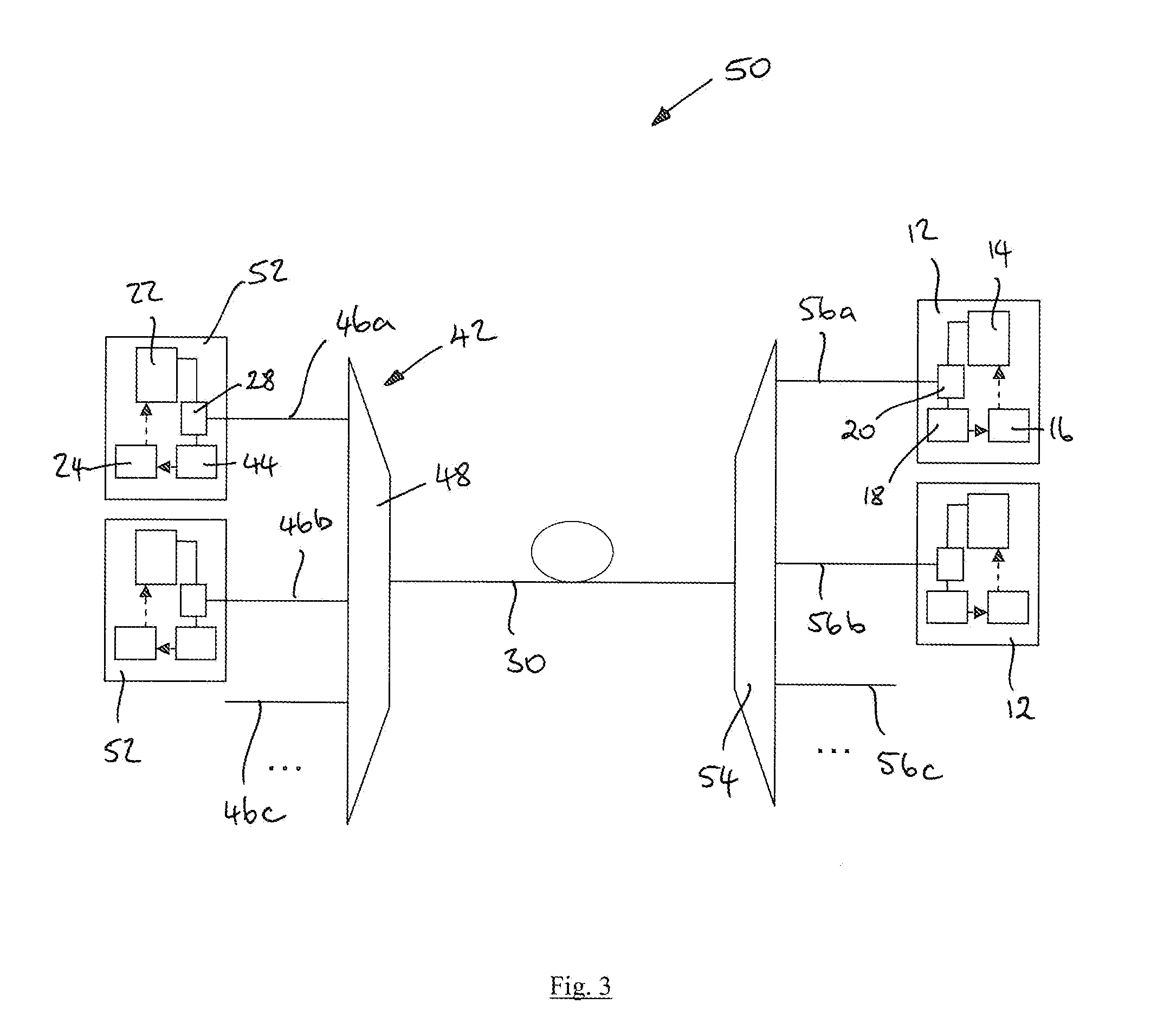
[0083]Referring to FIG. 3, the invention provides an optical network 50 which is substantially the same as the optical network 40 of the previous embodiment, with the following modifications. The same reference numbers are retained for corresponding features.

[0084]In this embodiment, the optical network 50 comprises a plurality of optical network elements 12, each coupled to the optical link 30 via a second wavelength selective router 54, which in this example comprises a second AWG. Each optical network element 12 is connected to a respective output port 56a, 56b, 56c of the AWG 54.

[0085]As shown in FIG. 4, the AWG 54 is a cyclic AWG, a first wavelength range, λ1, λ2 to λN being used for downstream optical signals, i.e. the optical signals from the respective second optical transmitters 22, and a second wavelength range, λN+1 to λ2N, being used for upstream optical signals, namely the first optical signals. The two wavelength ranges are separated by the free spectral range (FSR) of...


PUM

PropertyMeasurementUnit
wavelengthsaaaaaaaaaa
wavelengthaaaaaaaaaa
threshold optical poweraaaaaaaaaa

Abstract

An optical network (10) comprising an optical network element (12) comprising a first optical transmitter (14), a first controller (16), an optical receiver (18), a second optical transmitter (22), a second controller (24) and optical receiver apparatus (26). Said first controller is arranged to control said first optical transmitter to generate and transmit a first optical signal in response no second optical signal being detected. Said first controller is arranged to iteratively generate and transmit said first optical signal at different wavelengths of a plurality of wavelengths until said second optical signal is detected, and is further arranged to subsequently maintain generation and transmission of said first optical signal at said wavelength at which said second optical signal is detected. Said second controller is arranged to control said second optical transmitter to generate and transmit said second optical signal following detection of said first optical signal by said optical receiver apparatus.

Description

FIELD OF THE INVENTION[0001]The invention relates to an optical network, an optical network element, an optical line termination, a method of configuring an optical transmitter in an optical network and a method of remotely setting a wavelength of an optical transmitter in an optical network.BACKGROUND OF THE INVENTION[0002]Optical network technology is moving towards providing fibre to the home utilizing wavelength division multiplexing (WDM). One particular solution for fibre to the home is wavelength division multiplexed passive optical networks (WDM-PON) in which a separate wavelength channel is used to communicate from the central office (CO) optical line termination (OLT) to the optical network unit (ONU) at each home. This approach creates a virtual point-to-point link between the CO and each ONU, in contrast to the point to multipoint topology of a regular PON. The WDM-PON network architecture requires that each ONU transmits upstream on a different wavelength. Providing eac...

Claims


Application Information

Patent Timeline
Patent Type & Authority Applications(United States)
IPC IPC(8): H04J14/02H04B10/08
CPCB01J6/002C10J2300/0986B01J19/28B01J2219/182B01J2219/187B01J2219/1943B65G33/22C10B7/10C10J3/00C10J3/005C10J2200/158C10J2300/0916C10J2300/092C10J2300/0956C10J2300/0966C10J2300/0969B01J19/20H04J14/00H04B10/272H04J14/0221H04J14/0246H04J14/0257H04J14/0265H04J14/0267H04J14/0282H04B2210/071H04B10/0773H04Q11/0005H04Q2011/0016H04Q2011/0049H04Q2011/0083
Inventor CAVALIERE, FABIOGIORGI, LUCAGROSSO, RENATO
Owner TELEFON AB LM ERICSSON (PUBL)
Why Eureka
Try Eureka