Hydraulic fracture composition and method

a composition and fracture technology, applied in the field of hydraulic fracture composition and method, can solve the problems of hydrodynamic drag sweeping composition, and achieve the effects of minimizing preparation and introduction time on the surface at the well site, optimal elimination, and easy drawing

Active Publication Date: 2012-09-06
AQUASMART ENTERPRISES +1
View PDF8 Cites 46 Cited by
  • Summary
  • Abstract
  • Description
  • Claims
  • Application Information

AI Technical Summary

Benefits of technology

[0044]For example, a friction reducer, bioside, oxygen scavenger, clay stabilizer, scale inhibitor, gelling agent, or the like may be included in a mix, or as an element to be adhered to a substrate proppant. The substrate thereby forms particles that will easily be drawn into a flow of fracturing fluid, thus introducing all the necessary constituents into the flow. This occurs rapidly, without having to wait for mixing to occur topside on the site before introduction into the bore. Rather, mixing can take place and hydration or distribution in the flow may take place on the fly as the flow of fluid courses through the bore toward the formation. Thus, the preparation and introduction time on the surface at the well site is minimized.
[0045]In certain embodiments, the composition may be mixed directly into the fluid to form a complete and suitable fracturing fluid with all the necessary additives desired. By adhering chemicals to the proppant as the operable substrate, in the correct ratios, elaborate mixing ratios and elaborate mixing processes, and control thereof, as well as their related equipment, personnel, time, storage, and handling are greatly reduced, and optimally eliminated. Thus, the operational footprint of a service company on the well site is reduced, as well as the time, cost, labor, and so forth required to measure, add, mix, and otherwise introduce desired chemical constituents into the fracturing fluid.
[0046]By coat

Problems solved by technology

Meanwhile, the cross sectional area presented results in hy

Method used


Image

  • Hydraulic fracture composition and method
  • Hydraulic fracture composition and method
  • Hydraulic fracture composition and method

Examples


Embodiment Construction

[0061]It will be readily understood that the components of the present invention, as generally described and illustrated in the drawings herein, could be arranged and designed in a wide variety of different configurations. Thus, the following more detailed description of the embodiments of the system and method of the present invention, as represented in the drawings, is not intended to limit the scope of the invention, as claimed, but is merely representative of various embodiments of the invention. The illustrated embodiments of the invention will be best understood by reference to the drawings, wherein like parts are designated by like numerals throughout.

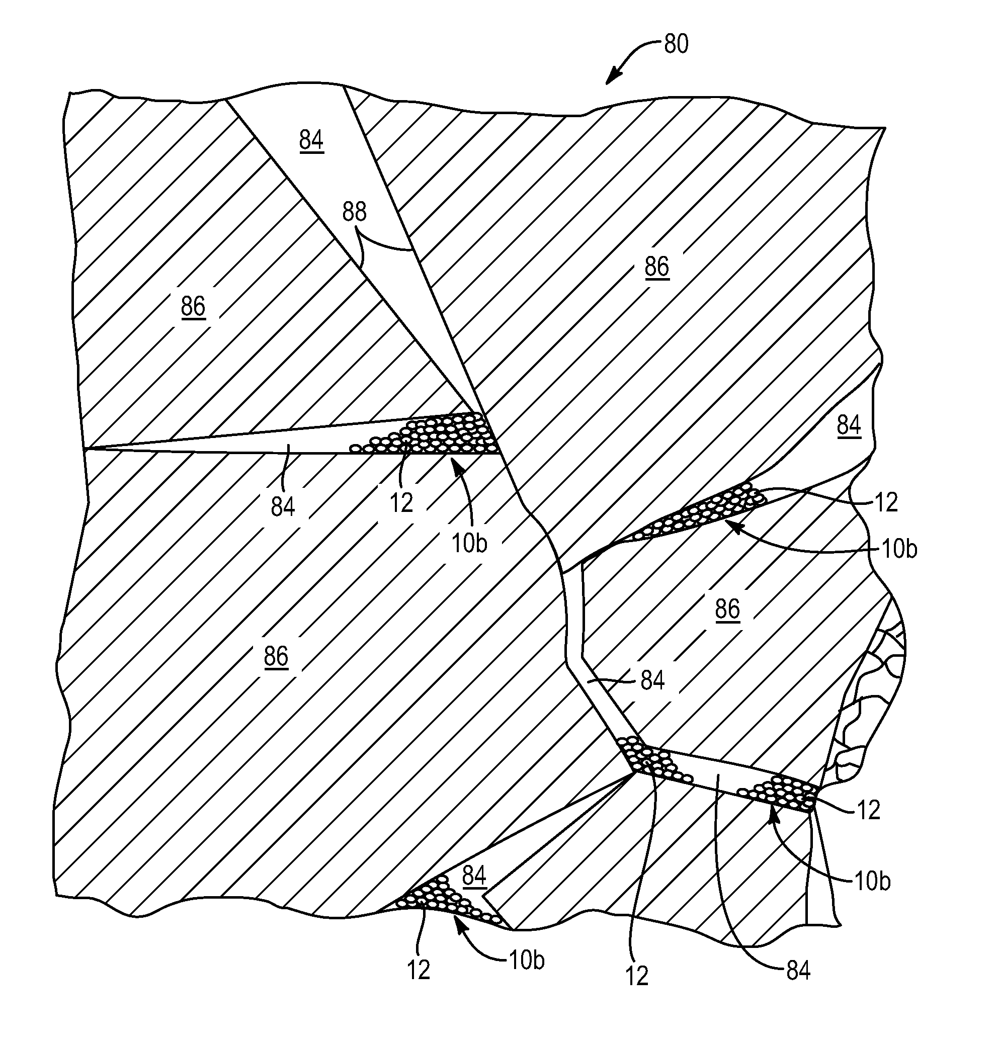
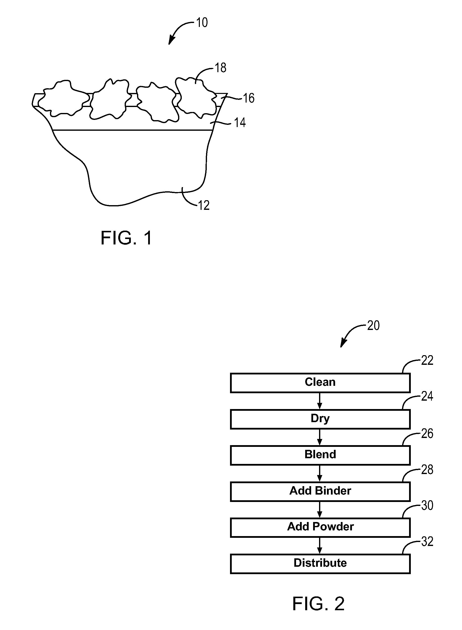
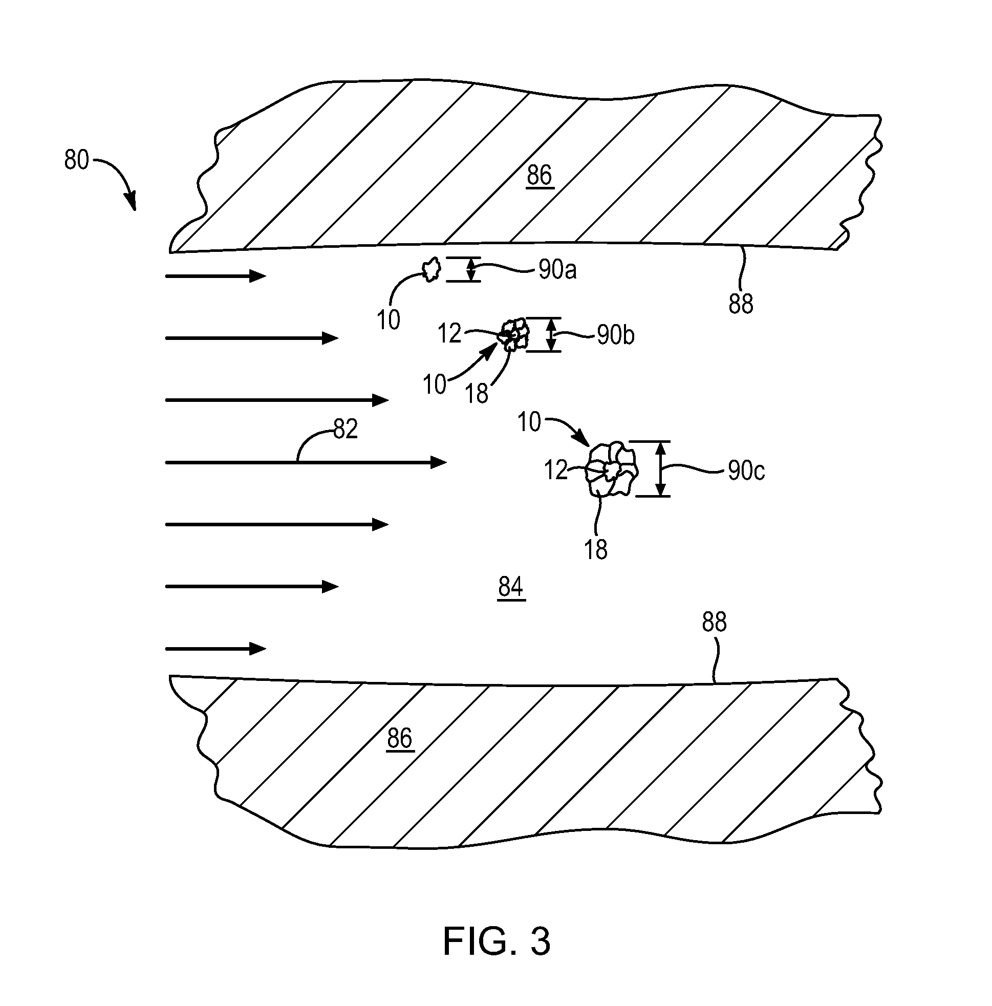
[0062]Referring to FIG. 1, a material 10 in accordance with the invention may include a substrate 12 formed of a suitable material for placement in the vicinity of a fracture region. For example, a substrate may be a particle of sand, ceramic sand, volcanic grit, or other hard material. In some embodiments, a substrate may be fo...


PUM


Abstract

A method for improving hydraulic fracturing creates coated proppants containing one or more chemical constituents bonded to a substrate and introduced into the fracturing fluid itself. The substrate that eventually acts as a proppant may be sand, ceramic, resin coated sand, and other materials. Typically, the materials that are coated as powders adhered to the substrate may include friction reducers, biosides, oxygen scavengers, clay stabilizers, scale inhibitors, gelling agents, or the like. By adhering solid materials to a substrate 12 by a binder 14, a single, solid, granular material may be maintained onsite, requiring reduced footprint, reduced mixing and may introduce almost instantaneously into a fracturing flow stream all the necessary chemical constituents, which will eventually become mixed. The result is reduced time, energy, manpower, equipment, and space at the sight, while reducing the environmental impact of transportation, spills, hydrocarbon use, and the like.

Description

RELATED APPLICATIONS[0001]This application is a continuation-in-part of U.S. patent application Ser. No. 13 / 299,288, filed Nov. 17, 2011, which is a continuation-in-part of U.S. patent application Ser. No. 12 / 789,177, filed May 27, 2010, which is a continuation of U.S. patent application Ser. No. 12 / 324,608, now U.S. Pat. No. 7,726,070, issued Jun. 1, 2010 to Thrash, which claims the benefit of U.S. Provisional Patent Application Ser. No. 61 / 012,912, filed on Dec. 11, 2007.BACKGROUND[0002]1. The Field of the Invention[0003]This invention relates to oil field and oil well development, and, more particularly, to novel systems and methods for fracturing and propping fissures in oil-bearing formations to increase productivity.[0004]2. The Background Art[0005]Oil well development has over one hundred years of extensive engineering and chemical improvements. Various methods for stimulating production of well bores associated with an oil reservoir have been developed. For example, United S...

Claims


Application Information

Patent Timeline
IPC IPC(8): C09K8/80C09K8/52
CPCA01N25/34C09K8/805E21B43/267
Inventor HENDRICKSON, CALDER
Owner AQUASMART ENTERPRISES
Why Eureka
Try Eureka