Low cost sun tracking pole mount for solar panels

Inactive Publication Date: 2012-09-13
ADVANCED TECH & RES CORP
View PDF13 Cites 21 Cited by
  • Summary
  • Abstract
  • Description
  • Claims
  • Application Information

AI Technical Summary

Benefits of technology

[0013]This invention presents a unique design of a solar tracker that is a pole mounted, equatorial or “polar mount” style tracker, and it is inexpensive to build and optimized for installation on conventional light poles. The mechanical simplicity and low cost are critical to an overall concept of providing a cost effective solu

Problems solved by technology

However, it would require a level of final fitting in the field and the design will not support sun tracking for the solar panel.
The solar panel cannot pivot and the mount brackets supporting the panel are not oriented in a manner that could support a simple rack and pinion drive mechanism.
The clamping arrangement for securing the fixed brackets to the poles is also limited in their ability to accommodate different pole sizes and shapes.
The clamping arrangement is similarly

Method used


Image

  • Low cost sun tracking pole mount for solar panels
  • Low cost sun tracking pole mount for solar panels
  • Low cost sun tracking pole mount for solar panels

Examples


Embodiment Construction

[0026]The following sections describe only one embodiment of this invention where the application is for a solar panel tracking system. It should be obvious that this invention could be utilized for a variety of other point applications that required an equatorial path for aiming.

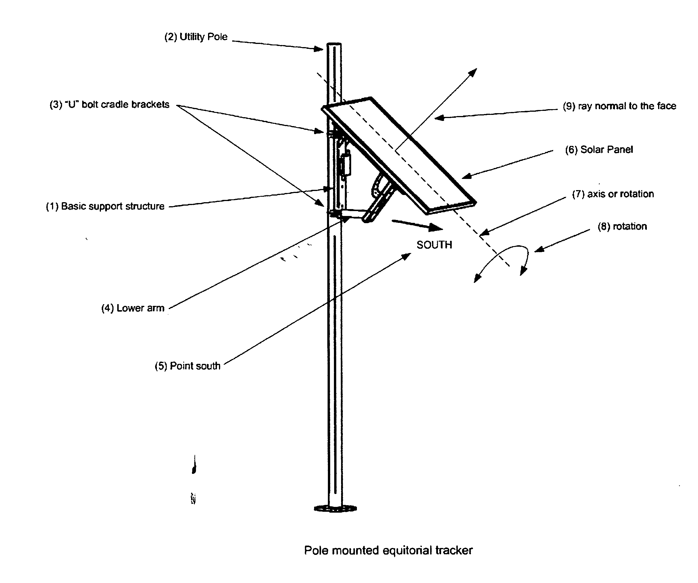
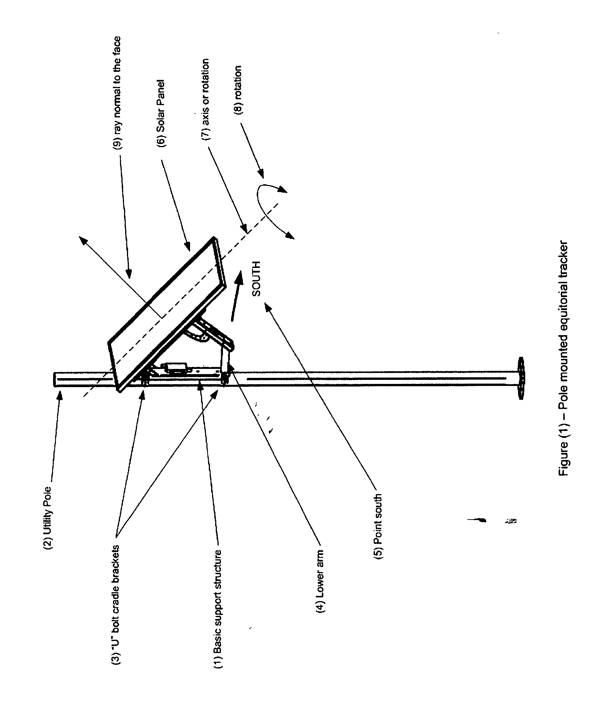
[0027]FIG. (1) shows the pole mounted equatorial tracker and how it is installed on a representative pole. The basic support structure (1) is attached to the utility pole (2) using one or more “U” bolt cradle brackets (3). The support structure (1) is attached to the utility pole (2) so that the torque tube (4) of the lower arm is pointed due south (5). The Solar panel (6) is mounted on a support frame (not shown) that has an axis of rotation (7). The inclination of this axis of rotation (7) and the south facing orientation of the support structure (1) will result in the axis being parallel to the axis of rotation of the earth. This is the common mechanical definition of an equatorial or polar mount trackin...


PUM


Abstract

This invention presents a robust and low cost design for a sun tracking, solar panel mounting system that can be mounted on a wide range of light poles and power poles. This design incorporates a structural base that is attached to the pole with separate “U” bolts and custom cradles that precisely accommodate the mounting pole dimensions. The structural base incorporates an axle and separate pivoting frame to hold the solar panel and allow it to rotate about the axle in a celestial tracking configuration known as an equatorial mount. A simple automotive style electric motor in the support arm interfaces with a curved gear rack of the pivoting frame to power the motion of the solar panel and frame. A control system coordinates the movement of the frame to achieve the sun tracking.

Description

BACKGROUND OF THE INVENTION[0001]1. Field of the Invention[0002]This invention relates to solar energy electrical power collection systems and specifically to the design of a low cost, sun tracking mount, designed specifically for utility power poles, light poles, and other pole supported structures.[0003]Utility poles for lighting, power, and communications are prevalent in today's landscape. They are existing industrial structures that can be utilized to support light weight appendages and most are also connected to the local electrical power grid. These are attractive features for the location of solar panels and solar power collection systems. Using existing light poles for a mounting structure greatly reduces the cost to install the solar panels and no additional real estate is required. Utilizing existing utility poles also provides an easy access to the electrical grid so that power produced by the solar panels does not need to be stored but can be “sold” back to the grid for...

Claims


Application Information

Patent Timeline
IPC IPC(8): H01L31/052F24S50/20
CPCY02E10/50F24J2/523H02S20/00F24J2002/4663Y02E10/47F24J2/5413F24S25/10F24S30/428F24S2025/6003H02S20/30H02S20/32
Inventor LUNDAHL, ROBERT D.CUTLIP, ROBERT WESLEYFINCH, WILLIAM
Owner ADVANCED TECH & RES CORP
Why Eureka
Try Eureka