Gas filling system, gas filling method, and vehicle

Active Publication Date: 2012-09-13
TOYOTA JIDOSHA KK
View PDF4 Cites 38 Cited by
  • Summary
  • Abstract
  • Description
  • Claims
  • Application Information

AI Technical Summary

Benefits of technology

[0009]According to the aspects of the invention, the heat radiation performance of the gas tank may be acquired from a temperature increase and a pressure increase, and a filling rate map is selected on the basis of the acquired heat radiation performance. Thus, it is possible to carry out gas filling at a filling rate suitable for the gas tank. By so doing, a predetermined filling amount (a filling amount in the case of full filling and a filling amount in the case of specified amount filling) may be filled in a short period of time as much as possible while the inside of the gas tank is kept stable. In addition, the heat radiation performance of the gas tank is acquired from a calculated temperature increase and a calculated pressure increase, so it is not necessary to store the heat radiation performance of

Problems solved by technology

However, the technique described in JP-A-2007-147005, the heat radiation property of a gas tank and a period of time for filling are not considered, so there is s

Method used


Image

  • Gas filling system, gas filling method, and vehicle
  • Gas filling system, gas filling method, and vehicle
  • Gas filling system, gas filling method, and vehicle

Examples


first alternative embodiment

[0060]As shown in FIG. 4, steps S14 and S15 may be used instead of steps S4 to S6 shown in FIG. 3. Note that steps S11 to S13 and S16 shown in FIG. 4 are the same as steps S1 to S3 and S7 shown in FIG. 3, so the description thereof is omitted.

[0061]In step S14, a filling rate map is selected from the filling rate map group on the basis of the increase ratio ΔT / ΔP and the tank initial pressure. As shown in FIG. 5 that shows an example of the filling rate map group used in this case, a filling rate map group MM defines a plurality of filling rate maps using the tank initial pressure for the ordinate axis and the increase ratio ΔT / ΔP for the abscissa axis. Here, the tank initial pressure and the increase ratio ΔT / ΔP are set for each of three ranges to define nine filling rate maps Ma to Mi in total. However, of course, these may be appropriately changed in design. In step S14, for example, when the increase ratio ΔT / ΔP is smaller than the threshold A and the tank initial pressure is 10...

second alternative embodiment

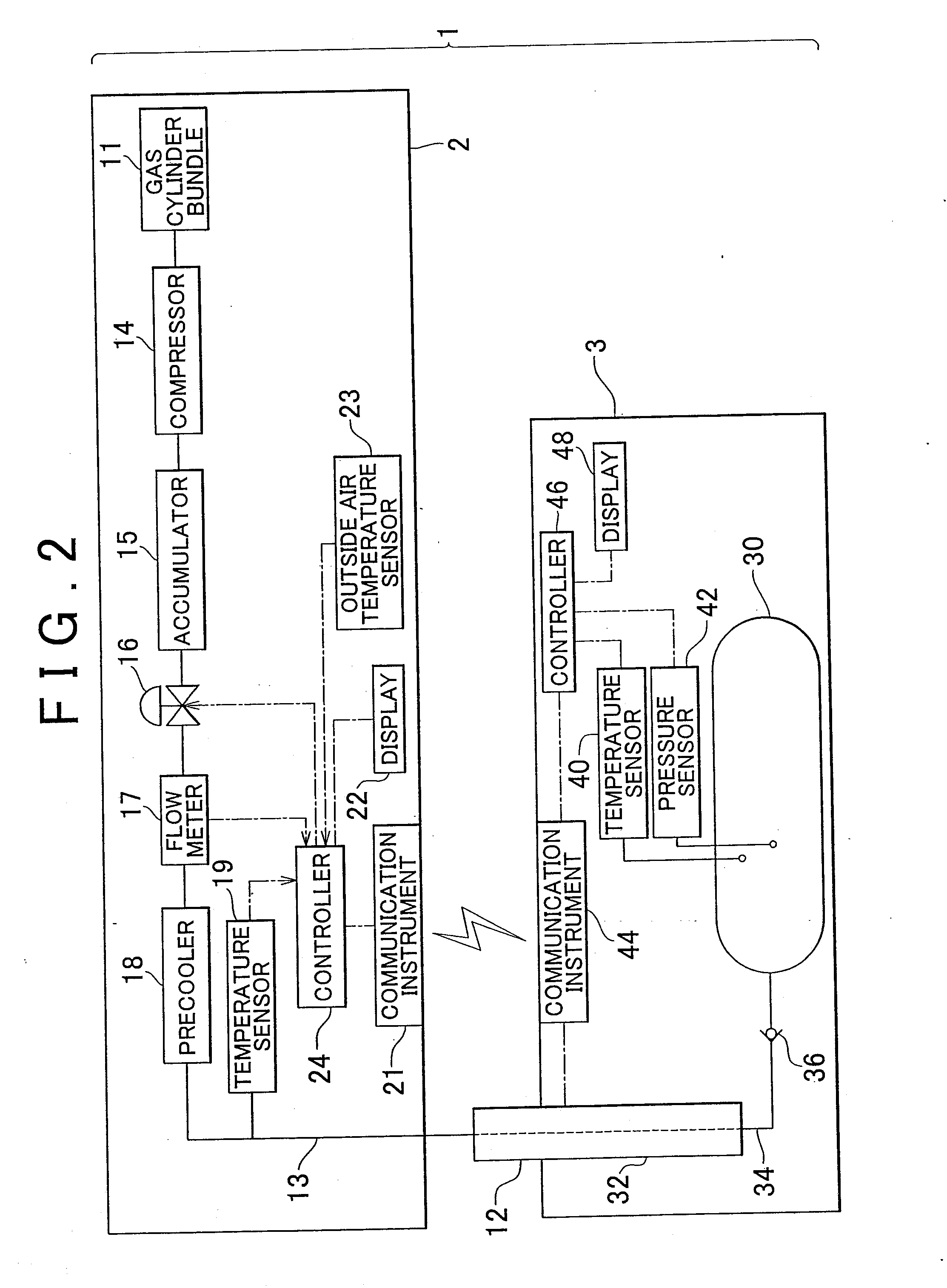
[0069]In the gas filling system 1, the step of calculating the tank temperature increase ΔT and the tank pressure increase ΔP (step S3 in FIG. 3, step S13 in FIG. 4) and the step of selecting a filling rate map thereafter (steps S4 to S6 in FIG. 3, steps S14 and S15 in FIG. 4) may be executed by separate controllers. For example, it is applicable that the former calculation step is executed by the controller 46 at the side of the vehicle 3, the calculation result is transmitted to the gas filling device 2 through communication, and then the latter selecting step is executed by the controller 24. In this case, a computation unit corresponding to the above described computation unit 62 is included in the controller 46.

[0070]Different from this, it is also applicable that, in the gas filling system1, the calculation step and the selecting step (steps S3 to S6 in FIG. 3, steps S13 to S15 in FIG. 4) are executed by the controller 46 at the side of the vehicle 3. In this case, the filling...

third alternative embodiment

[0072]In a third alternative embodiment, the location of the temperature sensor 19 that detects the precooler temperature may be changed. It is only necessary that the temperature sensor 19 is able to detect the temperature of hydrogen gas between the precooler 18 and a portion upstream of the gas tank 30, so the temperature sensor 19 may be provided for the receptacle 32 or the filling conduit 34 at the side of the vehicle 3 or may detect the temperature of hydrogen gas discharged from the gas filling device 2 toward the gas tank 3. In addition, in another embodiment, the temperature sensor 19 may be provided for the filling nozzle 12 and may detect the temperature of hydrogen gas at the filling nozzle 12.

[0073]The gas filling system and gas filling method according to the aspect of the invention may be not only applied to hydrogen gas but also applied to a gas that increases in temperature during filling. In addition, the gas filling system and the gas filling method may be not on...


PUM


Abstract

A gas filling system (1) includes a gas tank (30); a gas filling device (2) that fills gas into the gas tank (30); and a controller (24) that calculates a temperature increase ΔT and a pressure increase ΔP in the gas tank (30) during a predetermined period of time (t seconds) that elapses from a start of gas filling. The controller (24) selects a filling rate map (Ma, Mb) from a prepared filling rate map group on the basis of the calculated temperature increase ΔT and the calculated pressure increase ΔP. The gas filling device (2) carries out gas filling using the filling rate map selected by the controller (24).

Description

BACKGROUND OF THE INVENTION[0001]1. Field of the Invention[0002]The invention relates to a gas filling system that fills a gas tank mounted on, for example, a vehicle with gas from a gas filling device installed in, for example, a hydrogen station.[0003]2. Description of the Related Art[0004]A vehicle equipped with a gas tank makes a stop at a gas station for gas filling, and gas is filled into the gas tank from a filling nozzle of a gas filling device. In the case of hydrogen gas, the temperature and pressure increase in the gas tank as the hydrogen gas is filled into the gas tank, so it is necessary to regulate the filling amount so that these temperature and pressure do not exceed respective reference values. In terms of this point, Japanese Patent Application Publication No. 2007-147005 (JP-A-2007-147005) describes a technique that the temperature in a hydrogen tank is measured during hydrogen filling and then a filling path is changed to a filling path with a precooler when the...

Claims


Application Information

Patent Timeline
IPC IPC(8): B65B1/30
CPCF17C5/06Y02E60/324F17C2201/058F17C2203/0604F17C2203/0646F17C2203/0658F17C2205/0134F17C2205/0326F17C2205/037F17C2221/012F17C2223/0123F17C2223/035F17C2225/0123F17C2225/035F17C2227/0157F17C2227/0341F17C2227/039F17C2250/032F17C2250/034F17C2250/043F17C2250/0439F17C2250/0443F17C2250/0491F17C2250/0495F17C2250/0636F17C2250/0694F17C2260/025F17C2260/026F17C2265/065F17C2270/0105F17C2270/0168F17C2270/0184F17C2270/0189F17C2270/05Y02E60/321F17C2201/056Y02E60/32
Inventor MORI, TOMOYUKI
Owner TOYOTA JIDOSHA KK
Why Eureka
Try Eureka