Magnetic field sensor, as well as magnetic field measurement method, power measurement device, and power measurement method using the same

a technology of magnetic field and power measurement method, which is applied in the direction of galvano-magnetic hall-effect devices, instruments, electric devices, etc., can solve the problems of unnecessary energy consumption, high cost, and large size of power meters of this type in devices, and achieve simple configuration, high reliability, and simple

Inactive Publication Date: 2012-09-13
PANASONIC INTELLECTUAL PROPERTY MANAGEMENT CO LTD
View PDF0 Cites 13 Cited by
  • Summary
  • Abstract
  • Description
  • Claims
  • Application Information

AI Technical Summary

Benefits of technology

[0019]The present invention has been made in view of the above circumstances, and an object of the present invention is to provide a magnetic field sensor that can determine the positive and negative directions, and detect the magnetic field with high reliability.
[0020]Another object of the present invention is to provide a power measurement device that can easily measure an electric power without separate measurement of a power factor.Means for Solving the Problem
[0051]As described above, according to the magnetic field sensor of the present invention, because a voltage is extracted from points perpendicular to the element current direction with an extremely simple configuration, a direction of a magnetic field can be detected, and a magnetic field can be detected with high reliability.
[0052]Also, according to the magnetic field sensor of the present invention, the electric power can be extracted directly by extracting the DC component of the output voltage with the extremely simple configuration with no need to separately measure the power factor.

Problems solved by technology

However, the power meter of this type is not only upsized in device, but also expensive, and would also consume an unnecessary energy.

Method used


Image

  • Magnetic field sensor, as well as magnetic field measurement method, power measurement device, and power measurement method using the same
  • Magnetic field sensor, as well as magnetic field measurement method, power measurement device, and power measurement method using the same
  • Magnetic field sensor, as well as magnetic field measurement method, power measurement device, and power measurement method using the same

Examples


first embodiment

[0090]The magnetic field sensor according to a first embodiment will be described. FIG. 2 illustrates an illustrative view of a principle of the magnetic field sensor, FIG. 3 illustrates a top view thereof, and FIG. 4 illustrates a cross-sectional view thereof. As illustrated in FIGS. 3 and 4, a silicon oxide film is formed as an insulating film 2 on a surface of a substrate 1 made of silicon, a loop pattern of the ferromagnetic thin film 3 having a ferromagnetic characteristic is formed on the insulating film 2, and a conductor pattern configuring feeders 5A and 5B along the diametric direction of the loop pattern, and a conductor pattern as detectors 5C and 5D formed in a direction perpendicular to a direction of the element current supplied from the feeders 5A and 5B are provided.

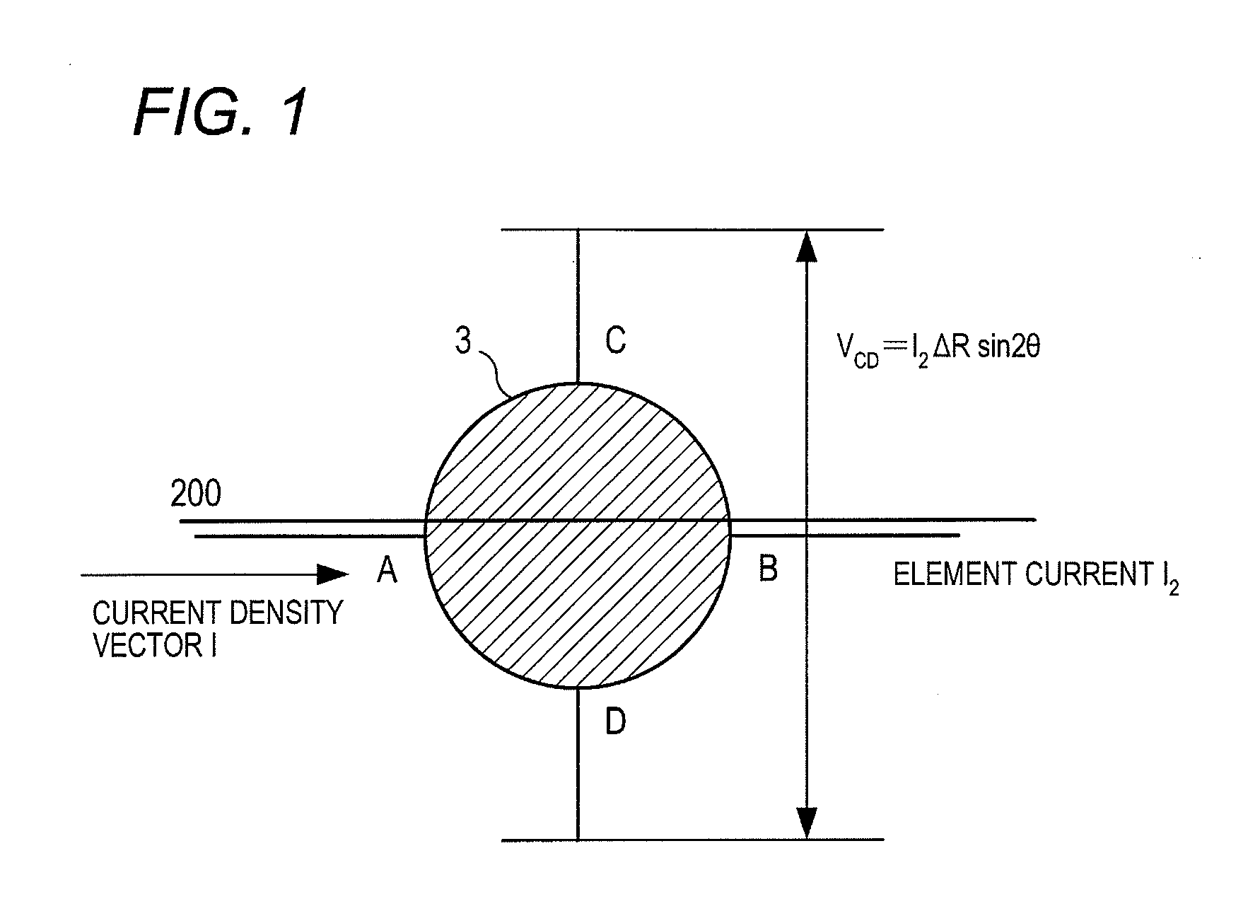
[0091]That is, as illustrated in the principle illustrative view of FIG. 2, the circular ferromagnetic thin film 3 is located symmetrically about the center of the pattern of the circular ferromagnetic t...

second embodiment

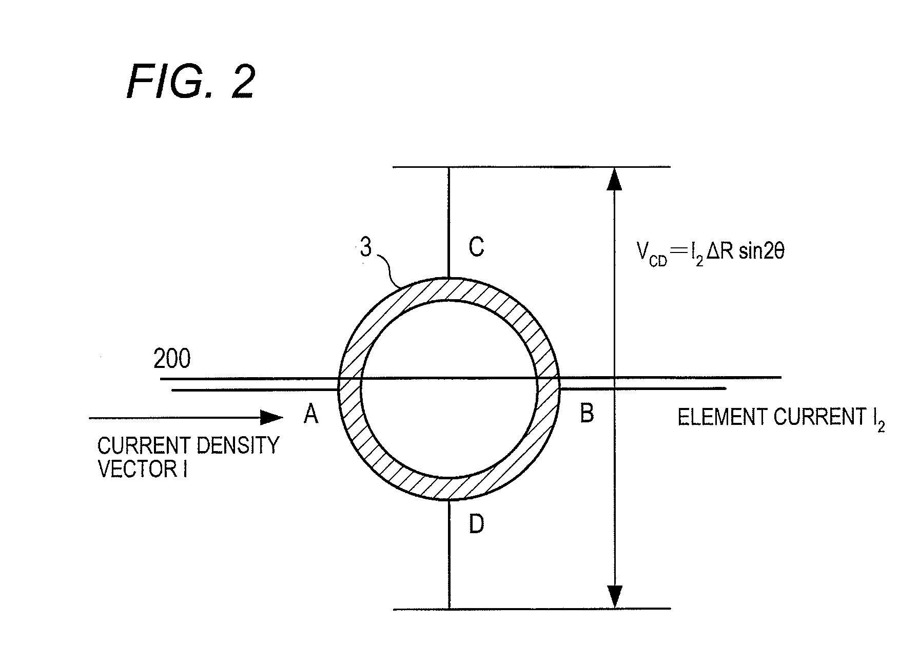
[0110]Subsequently, a second embodiment of the present invention will be described. In this embodiment, as illustrated in FIGS. 9 to 11, an auxiliary pattern 4 of a ferromagnetic thin film is formed as a circular inner magnetic thin film having a similar figure along an inner periphery of a ring of the ferromagnetic thin film 3 configuring the loop pattern of the magnetic field sensor in the first embodiment.

[0111]In this configuration, the auxiliary pattern 4 is merely added, and the other configurations are identical with those in the first embodiment, and their description will be omitted. The same parts are denoted by identical symbols. FIG. 9 illustrates an illustrative view of a principle of the magnetic field sensor, FIG. 10 illustrates a top view thereof, and FIG. 11 illustrates a cross-sectional view thereof. With presence of the auxiliary pattern 4, a magnetic sensitivity is enhanced while the electric resistance is kept high. An outer loop pattern that is the ferromagneti...

third embodiment

[0118]Subsequently, a third embodiment of the present invention will be described. In this embodiment, as illustrated in FIGS. 14 and 15, the ferromagnetic thin film is configured by a square loop pattern 33, the feeders 5A and 5B are located so that current flows in a diagonal direction of the square, and the detectors 5C and 5D are formed in a direction perpendicular to the diagonal direction.

[0119]Similarly, in this embodiment, the loop pattern 3 of the magnetic field sensor according to the first embodiment is merely replaced with the square loop pattern 33, and the other configurations are identical with those in the first embodiment, and their description will be omitted. The same parts are denoted by identical symbols. FIG. 14 is an illustrative view of a principle of the magnetic field sensor, and FIG. 15 is a top view thereof.

[0120]In this example, a magnetic flux density vector is a combination of the spontaneous magnetization vector M of the element and the external magne...


PUM


Abstract

A magnetic field sensor includes: a magnetic thin film; a feeder comprising an input and output terminals configured to supply element current to the magnetic thin film; and a detector configured to detect a voltage between ends of the magnetic thin film in a direction perpendicular to a direction of the element current. The magnetic thin film is Rained symmetric about the direction of the element current.

Description

TECHNICAL FIELD[0001]The present invention relates to a magnetic field sensor, a magnetic field measurement method using the magnetic field sensor, a power measurement device, and a power measurement method, and more particularly to a power measurement device that extracts a voltage of a magnetic field sensor for realizing a magnetic field measurement with high precision, and using the magnetic field sensor.BACKGROUND ART[0002]In recent years, the development of a measurement system including remote power meter reading has been forwarded in environment where the Internet is available.[0003]There is used a power meter using a method in which a sensor that detects rotation is added, or an ammeter (CT) and a voltmeter (PT) are newly added to an existing integrating power meter that converts a used electric power into the number of rotations of a disc, and conducts integration operation, and multiplicative computation is conducted by an electric circuit or a microprocessor to measure th...

Claims


Application Information

Patent Timeline
Patent Type & Authority Applications(United States)
IPC IPC(8): G01R33/05G01R21/00
CPCH01L43/06G01R33/09H10N52/00G01R21/08H10N50/10
Inventor TAKENAGA, HIDEKIIWAMI, EIJISAWADA, TOMOYUKITSUJIMOTO, HIROAKIYOSHIKAWA, KEISUKEFUKUI, SUGURU
Owner PANASONIC INTELLECTUAL PROPERTY MANAGEMENT CO LTD
Why Eureka
Try Eureka