Rapid switchable HV P-MOS power transistor driver with constant gate-source control voltage

a technology of p-mos and power transistor, which is applied in the direction of logic circuits, pulse automatic control, electric pulse generators, etc., to achieve the effect of enhancing the switching speed minimizing static power dissipation of high voltage power transistors

Active Publication Date: 2012-09-13
DIALOG SEMICONDUCTOR GMBH
View PDF23 Cites 6 Cited by
  • Summary
  • Abstract
  • Description
  • Claims
  • Application Information

AI Technical Summary

Benefits of technology

[0011]A further object of the invention is to minimize static power dissipation of a high voltage power transistor.
[0012]Another object of the invention is to enhance switching speed of the high voltage power transistor.

Problems solved by technology

It is a challenge for engineers designing driver circuits for high voltage applications, i.e. supply voltages in the order of magnitude of 40 V to overcome above problems.

Method used


Image

  • Rapid switchable HV P-MOS power transistor driver with constant gate-source control voltage
  • Rapid switchable HV P-MOS power transistor driver with constant gate-source control voltage
  • Rapid switchable HV P-MOS power transistor driver with constant gate-source control voltage

Examples


Embodiment Construction

[0022]Methods and circuits to achieve an accurate control voltage of a high voltage power transistor combined with a rapid switching-on and switching-off operation of a high voltage power transistor are disclosed.

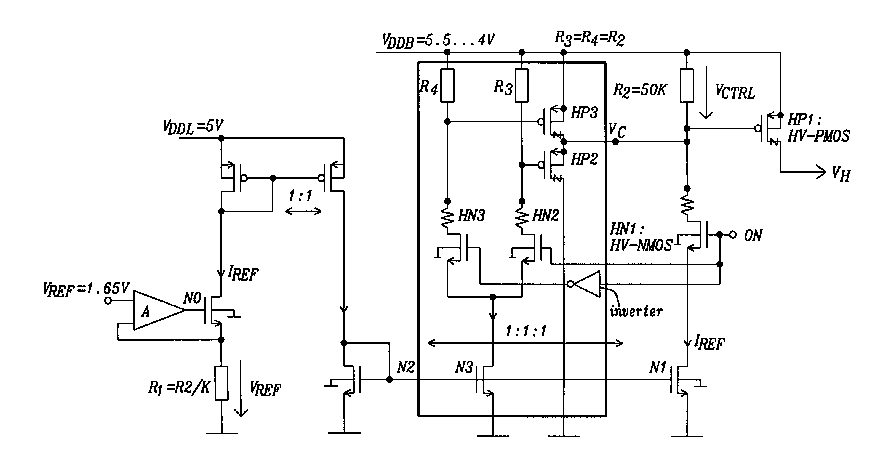
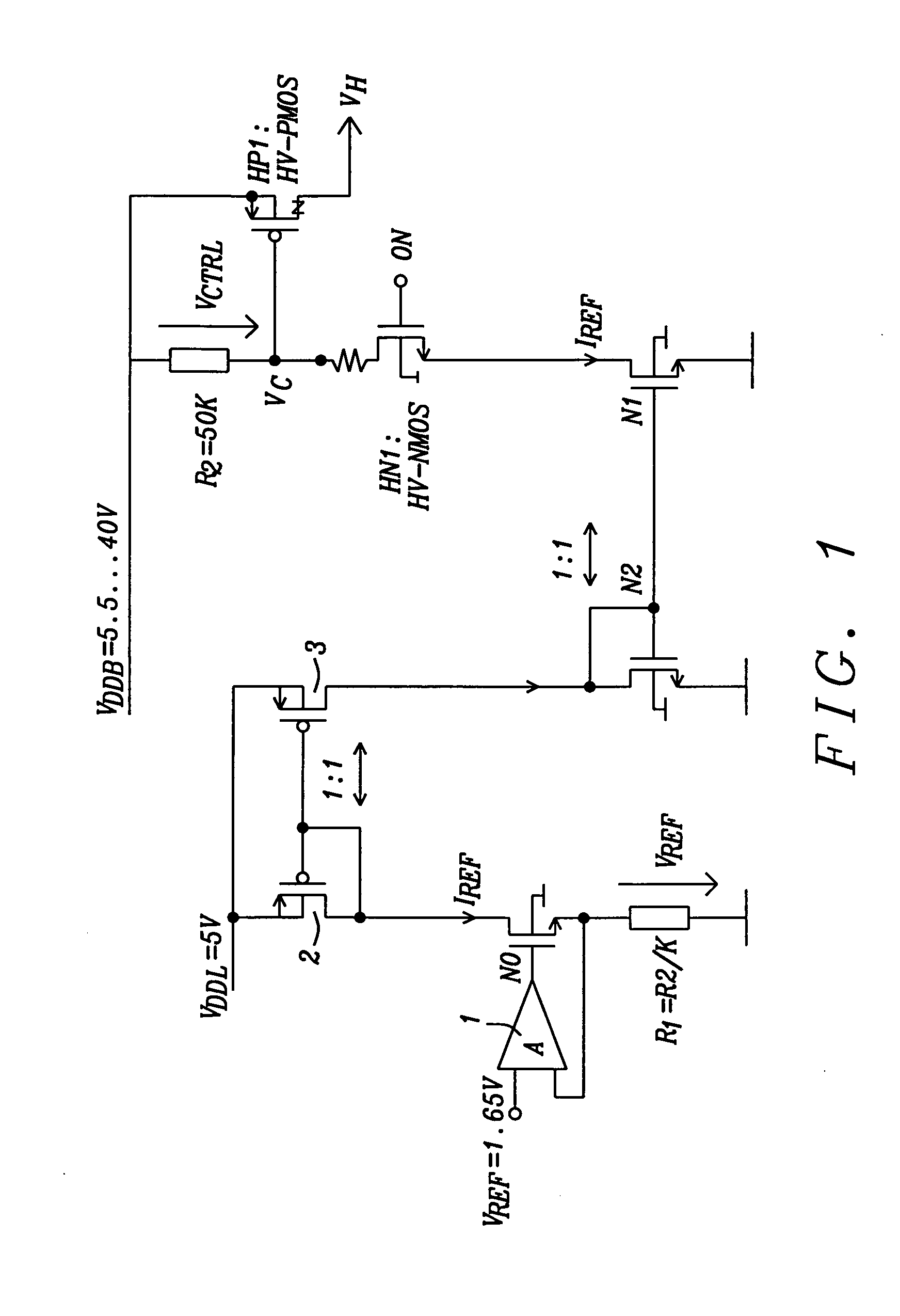
[0023]FIG. 1 shows principles of a preferred embodiment of the present invention, i.e. a schematic of a circuit driving a HV P-MOS power transistor (HP1). It should be noted that the invention could be applied to other power transistors with drain-source voltage capability higher than 5V and gate-source voltage limited to 5V.

[0024]The circuit shown in FIG. 1 to drive the HV P-MOS power transistor, HP1, is supplied directly by power supply, VDDB, with an input comprised of HV N-MOS transistor, HN1, directly controlled by 5V digital signal. In the preferred embodiment the power supply voltage VDDB can vary between 5.5 V and 40 V. Other ranges of voltages are possible as well, depending on e.g. the type of high voltage power transistor used. The HV power transistors deployed h...


PUM


Abstract

Systems and methods for providing a rapid switchable high voltage power transistor driver with a constant gate-source control voltage have been disclosed. A low voltage control stage keeps the gate-source voltage constant in spite of temperature and process variations. A high voltage supply voltage can vary between about 5.5 Volts and about 40 Volts. The circuit allows a high switching frequency of e.g. 1 MHz and minimizes static power dissipation.

Description

BACKGROUND[0001](1) Field of the Invention[0002]This invention relates generally to transistor drivers and relates more specifically to a driver for a high voltage P-MOS power transistor having accurate control voltage and faster switching.[0003](2) Description of the Prior Art[0004]For applications as e.g. automotive applications supply voltages up to 40 Volts and even higher are often required. High-Voltage CMOS devices are usually based on a 5V technology with an extended drain region to reach up to e.g. 40V drain-source breakdown capability. As the source side of the High-Voltage CMOS devices is the same as it is for 5-V CMOS devices, its bulk-source voltage, Vbs, as well as its gate-source voltage, Vgs, are limited to 5V. Static power dissipation of the high voltage (HV) transistors, achieving accurate control voltage of e.g. 5 Volts and high switching speed are key problems with high voltage CMOS devices, which should be overcome.[0005]It is a challenge for engineers designing...

Claims


Application Information

Patent Timeline
Patent Type & Authority Applications(United States)
IPC IPC(8): H03K3/00H03K5/08
CPCH03K17/04123H03K17/08122H03K2217/0063H03K19/018507H03K2217/0036H03K17/145
Inventor JI, CANG
Owner DIALOG SEMICONDUCTOR GMBH
Why Eureka
Try Eureka