
System and method for topology selection to minimize leakage power during synthesis

a topology selection and synthesis technology, applied in the field of electronic circuit design, can solve the problems of increasing area requirements, reducing circuit speed, and static power dissipation becoming a major design constraint, so as to minimize leakage power, and minimize static power dissipation

Inactive Publication Date: 2005-06-09
GLOBALFOUNDRIES INC
View PDF4 Cites 6 Cited by
  • Summary
  • Abstract
  • Description
  • Claims
  • Application Information

AI Technical Summary

Benefits of technology

The present invention provides a system and method for selecting the best topology for circuit gates to minimize leakage power during synthesis. The system takes advantage of the distinct leakage characteristics of different gate topologies to create an electronic circuit with reduced current leakage. The system also uses a traditional logic synthesis algorithm that takes into account the static leakage models. The leakage sensitivities of different topologies are calculated and used as a cost metric during optimization. The system synthesizes a new circuit model by selecting one or more of the topologies based on its leakage sensitivities. The new circuit model has reduced current leakage. The invention also includes a computer program product and a method for designing electronic circuits for reducing leakage power.

Problems solved by technology

Static power dissipation is becoming a major design constraint, not only in portable, but also in high performance very large-scale integrated (VLSI) systems.
This technique has a few disadvantages; however, such as decreased circuit speed due to the sleep transistor's resistance and increased area requirements for sleep signals and sleep transistors in a circuit design.
The problems associated with this technique are reduced performance and noise immunity if care is not exercised when designing the sleep transistors.
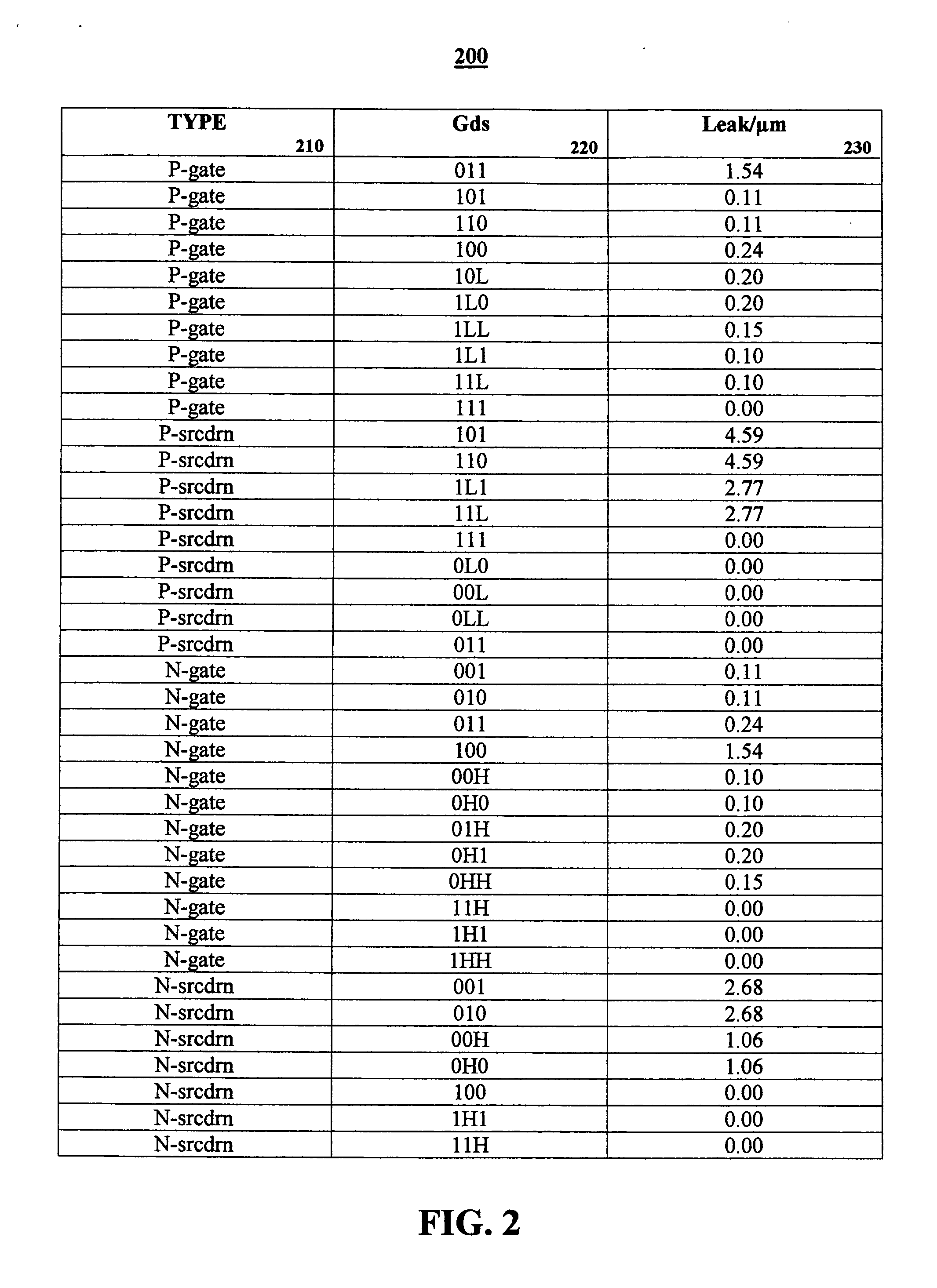
None of these techniques, however, take advantage of the fact that different gate topologies have different gate sensitivities for a unit width of a transistor size to its leakage current as an approach to topology selection.

Method used


Image

  • System and method for topology selection to minimize leakage power during synthesis
  • System and method for topology selection to minimize leakage power during synthesis
  • System and method for topology selection to minimize leakage power during synthesis

Examples


Embodiment Construction

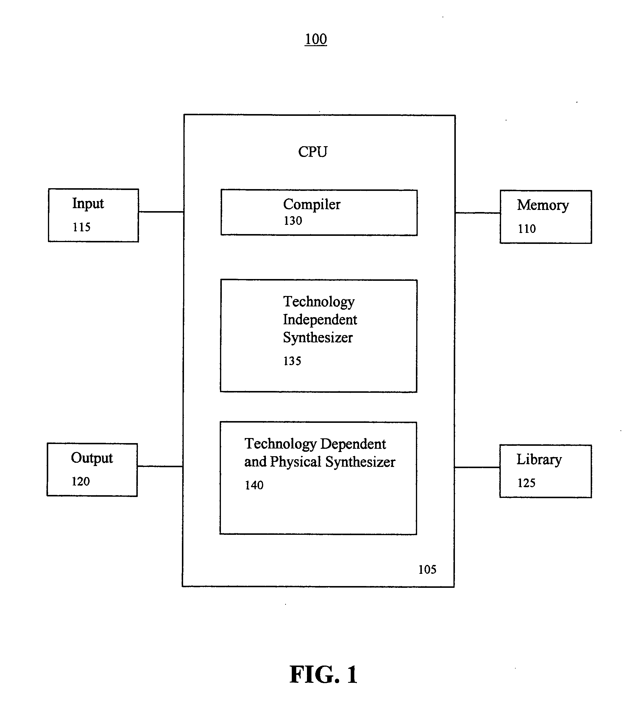
[0025]FIG. 1 illustrates an exemplary electronic circuit design system in accordance with the present invention. As shown in FIG. 1, an electronic circuit design system 100 includes, inter alia, a central processing unit (CPU) 105, a memory 110, an input 115, an output 120 and a library 125. The CPU 105 includes a compiler 130, a technology independent synthesizer 135 and a technology dependent and physical synthesizer 140.

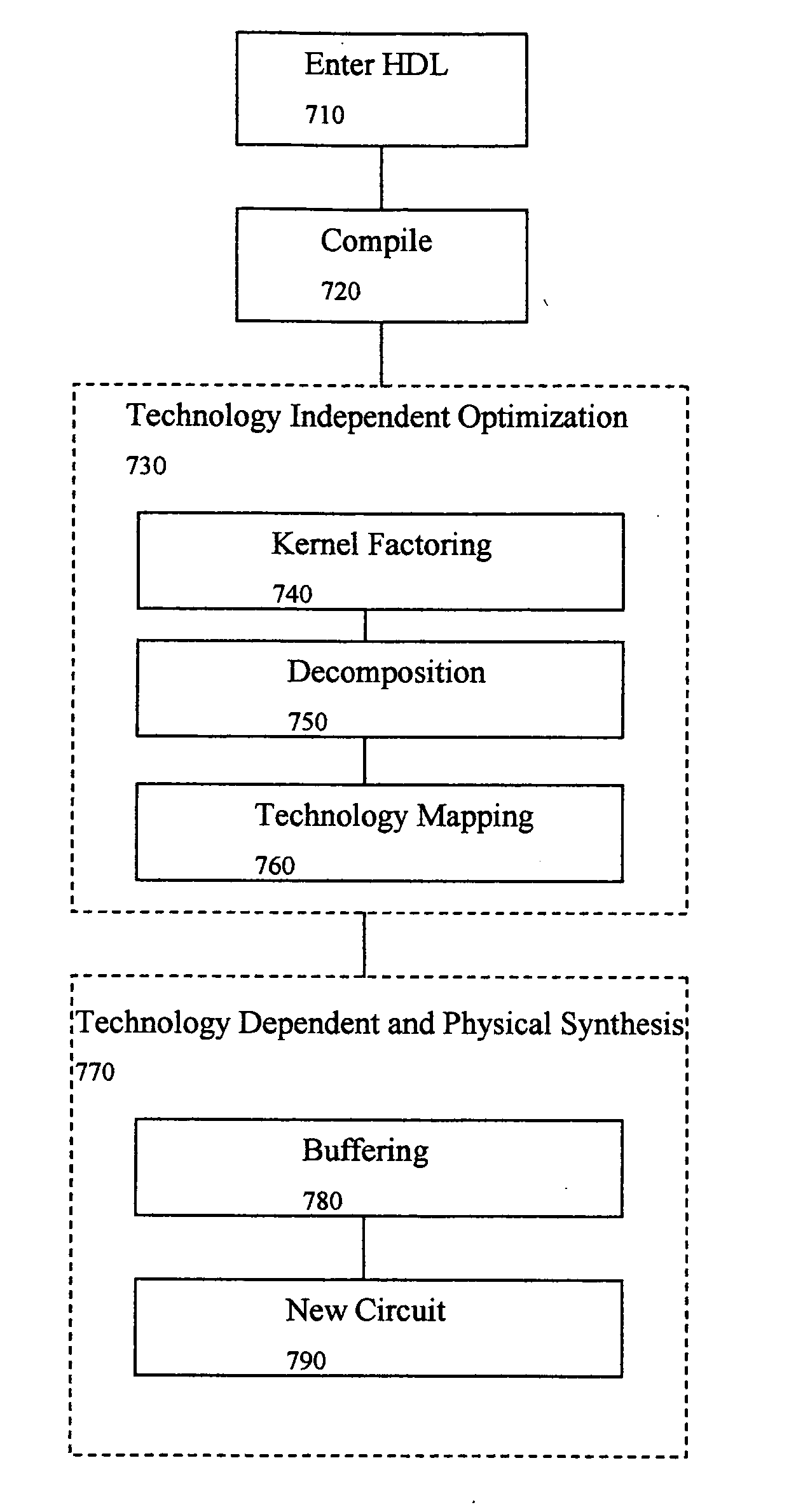
[0026] The compiler 130 has a function of compiling a High-level Design Language (HDL), where the HDL represents, for example, a design entered into the system by a user, into a logical network composed of logical blocks including equation blocks, functional blocks such as adders and multiplexers, and gates. The logical network is stored in the memory 110.

[0027] The technology independent synthesizer 135 has a function of performing technology independent optimization of the logical network. Here, the optimization does not initially consider concrete hardware co...


PUM


Abstract

A system for topology selection to minimize leakage power during synthesis, wherein the system is configured to receive a circuit model that has one or more circuit gates. The system is further configured to receive a library having one or more logic gates, wherein each logic gate has a topology and the leakage sensitivities for each of the topologies is calculated. The system is then configured to synthesize a new circuit model by selecting one or more of the topologies based on its leakage sensitivities, wherein the new circuit model has reduced current leakage.

Description

BACKGROUND OF THE INVENTION [0001] 1. Technical Field [0002] The present invention relates to electronic circuit design and more particularly, to topology selection of logic gates during synthesis of electronic circuits for minimizing leakage power. [0003] 2. Discussion of the Related Art [0004] Static power dissipation is becoming a major design constraint, not only in portable, but also in high performance very large-scale integrated (VLSI) systems. As static power dissipation exceeds dynamic power dissipation in high performance designs, synthesis techniques are being adapted to reduce leakage currents. [0005] Several techniques have been proposed to achieve leakage power reduction based on circuit-level optimization techniques. These techniques require architectural support, and in some cases, technology support, and are applied at run-time (i.e., dynamically) and can be divided into three different categories: (1) input vector control; (2) threshold variation; and (3) power sup...

Claims


Application Information

Patent Timeline
Patent Type & Authority Applications(United States)
IPC IPC(8): G06F17/50
CPCG06F17/505G06F30/327
Inventor JACOBSON, HANS M.KUDVA, PRABHAKAR N.SIGAL, LEON J.
Owner GLOBALFOUNDRIES INC
Learn More