Antenna structure and electronic device having the same

an antenna structure and electronic device technology, applied in the direction of antenna details, antennas, basic electric elements, etc., can solve the problems of electromagnetic waves that are potentially harmful to the brains of users, interfere with the electromagnets of other surrounding electronic devices, etc., and achieve the effect of reducing the frequency of the signal

Active Publication Date: 2012-09-13
AUDEN TECHNO
View PDF2 Cites 160 Cited by
  • Summary
  • Abstract
  • Description
  • Claims
  • Application Information

AI Technical Summary

Benefits of technology

[0009]For the above mentioned antenna structure and electronic device having the same, the SAR can be reduced

Problems solved by technology

However, electromagnetic waves off the electronic devices interfere with electromagnets of other surroundin

Method used


Image

  • Antenna structure and electronic device having the same
  • Antenna structure and electronic device having the same
  • Antenna structure and electronic device having the same

Examples


first embodiment

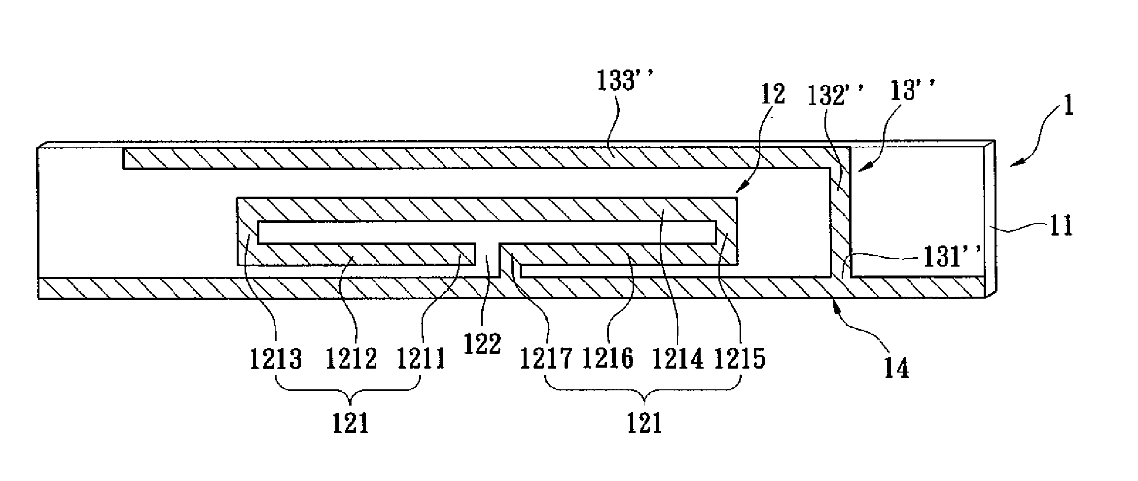
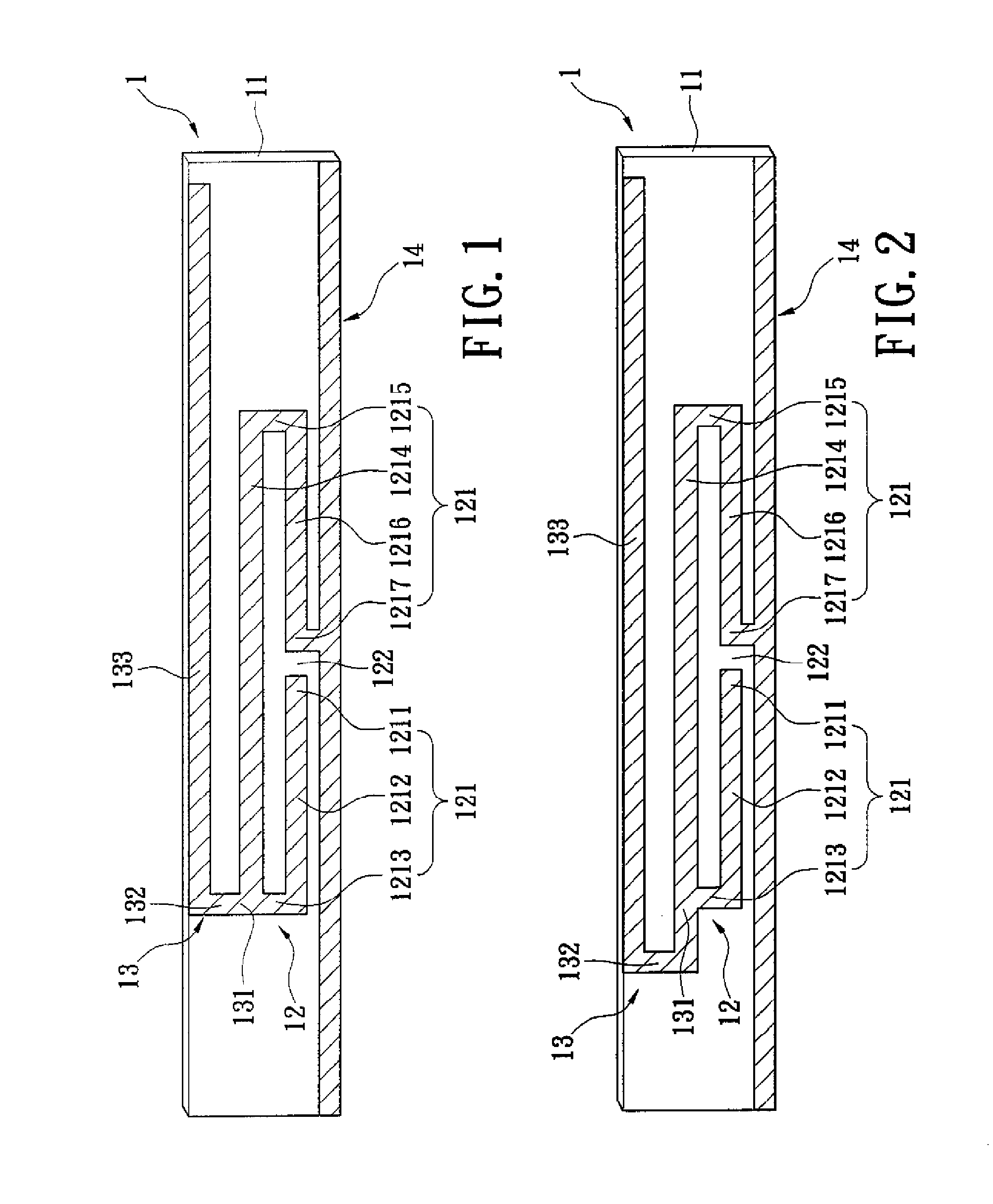
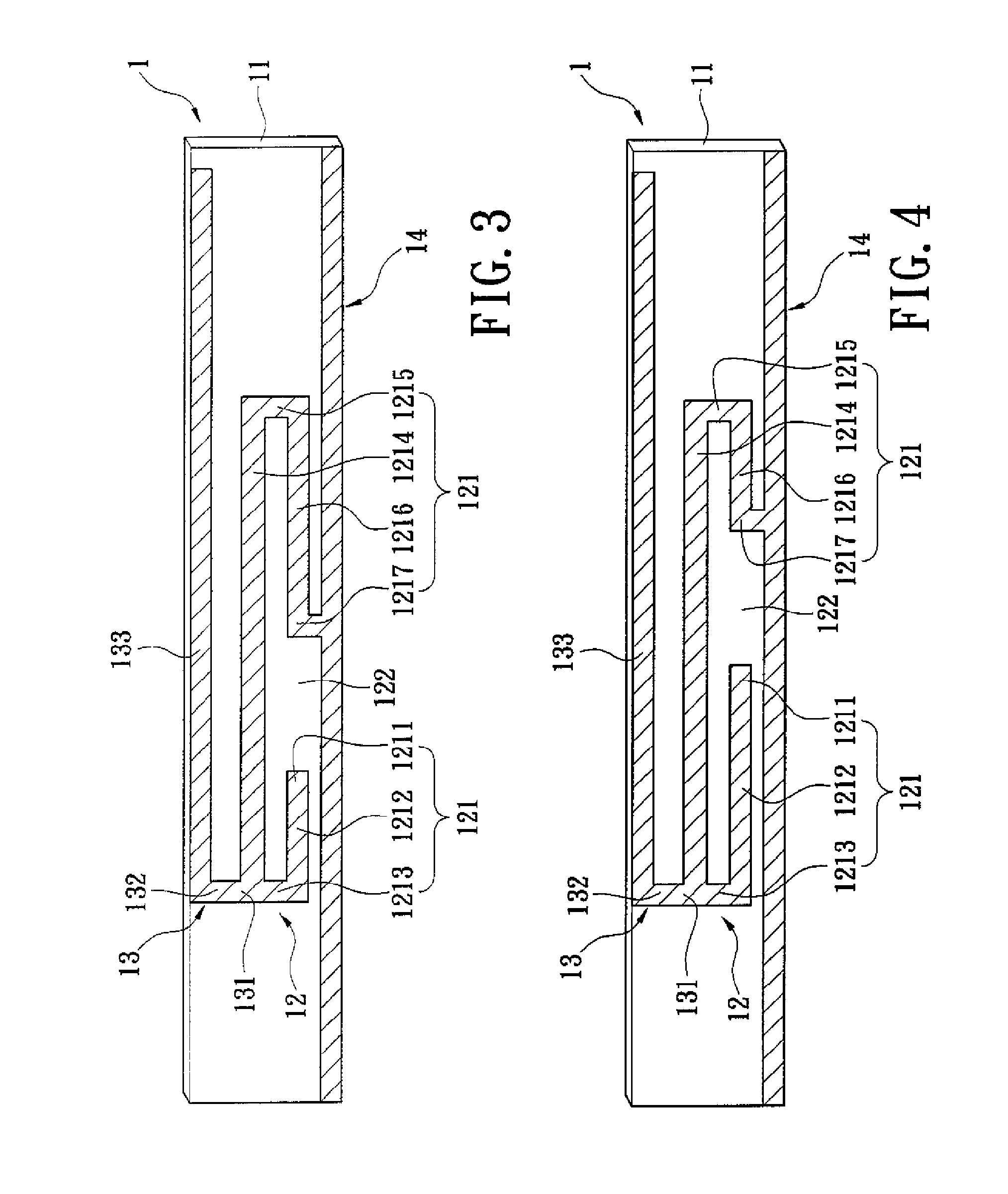
[0025]Please refer to FIGS. 1 to 7, which show the instant disclosure. As illustrated in FIGS. 1 and 2, an antenna structure 1 comprises a microwave substrate 11, wherein a first circuit 12, a second circuit 13, and a ground circuit 14 are disposed thereon. The microwave substrate 11 has two opposite faces, wherein one of the faces is disposed with the first circuit 12, the second circuit 13, and the ground circuit 14.

[0026]The first circuit 12 is an open loop structure 121 having a discontinuous portion 122. The first circuit 12 further has a pair of ends, namely a feed point 1211 and a ground point 1217, arranged respectively across the discontinuous portion 122. The ground point 1217 is connected to the ground circuit 14. From the feed point 1211, the first circuit 12 extends toward the ground point 1217 in forming a feed portion 1212, a sub-feed portion 1213, a connecting portion 1214, a sub-ground portion 1215, and a ground portion 1216.

[0027]The feed portion 1212, the sub-feed...

fifth embodiment

[0044]Please refer to FIGS. 13 and 14, which show the instant disclosure. The instant embodiment discloses an electronic device, which comprises an upper casing unit 2 for housing a display 3, a radio frequency (RF) module 4, and an antenna structure 1 on the inner thereof, and a lower casing unit 5 that matchingly coupled to the upper casing unit 2. The electronic device can be a tablet PC, but is not limited thereto. The encased antenna structure 1 of the instant embodiment is chosen from one of the above-described embodiments.

[0045]The display 3 is disposed at the central portion of the inner surface of the upper casing unit 2. The RF module 4 and the antenna structure 1 are disposed beyond the display 3, with the antenna structure 1 being connected to the RF module 4 by a cable 6. The preferred positions of the RF module 4 and the antenna structure 1 are determined arbitrarily. If the RF module 4 is close to the antenna structure 1, a shorter cable 6 can be used. Conversely, if ...


PUM


Abstract

An antenna structure is disclosed, which includes: a microwave substrate; and a first circuit, a second circuit, and a ground circuit disposed coplanarly on the microwave substrate. The first circuit is an open loop structure with a discontinuous portion and has a pair of ends, namely a feed point and a ground point, arranged respectively across the discontinuous portion. The ground point is connected to the ground circuit. The second circuit is disposed at the periphery of the first circuit, where the second circuit is connected to a connecting point of the first circuit on one side thereof. Thereby, the antenna structure reduces the SAR. In addition, an electronic device having an antenna structure is disclosed.

Description

BACKGROUND OF THE INVENTION[0001]1. Field of the Invention[0002]The instant disclosure relates to an antenna structure and electronic device having the same; more particularly, to an antenna structure for wireless communication, in terms of signal receiving and transmission, and electronic device having the same.[0003]2. Description of Related Art[0004]With continuing improvement in wireless technology, personal electronic devices are equipped with antenna structures in a widespread fashion. However, electromagnetic waves off the electronic devices interfere with electromagnets of other surrounding electronic devices. Health-wise, electromagnetic waves are potentially harmful to the brains of the users. Thus, the easing of electromagnetic wave interference and the reduction of specific absorption rate (SAR), defined as the rate at which the energy is absorbed by the human body under the influence of an electromagnetic field, are critical design considerations for antennas.[0005]With...

Claims


Application Information

Patent Timeline
IPC IPC(8): H01Q1/38H01Q1/24
CPCH01Q1/2266H01Q5/364H01Q1/245H01Q1/243
Inventor CHIANG, CHI-MING
Owner AUDEN TECHNO
Why Eureka
Try Eureka