
In-vehicle illuminating apparatus, image processing apparatus, and image displaying system

Active Publication Date: 2012-09-13
FUJITSU GENERAL LTD
View PDF5 Cites 41 Cited by
  • Summary
  • Abstract
  • Description
  • Claims
  • Application Information

AI Technical Summary

Benefits of technology

[0025]According to the configuration of (1) or (10), the light sources that illuminate the side area of the vehicle are accommodated in the housing in a state where the light axes of the light sources are directed to different directions from each other. Through this, the light sources are integrated by the housing, and the light sources for widely illuminating the side area of the vehicle can be mounted on the vehicle at low cost and simplicity.
[0026]In particular, according to the configuration of (1), the side area of the vehicle can be illuminated over a range from the front to the rear of the vehicle.
[0027]In particular, according to the configuration of (2), since the integrated light sources can be combined to both the left and right sides of the vehicle, the versatility is improved to reduce the cost.
[0028]In particular, according to the configuration of (3), by reducing the amount of light of the third light source to less than the amount of light of the first light source and the amount of light of the second light source, the side area of the vehicle can be substantially uniformly illuminated over a range from the front to the rear of the vehicle.
[0029]In particular, according to the configuration of (4), since the camera and the light sources to assist in image capturing through the camera are integrated by the housing, the camera and the light sources can be attached to the vehicle collectively and easily.
[0030]In particular, according to the configuration of (5), since the light sources can be selectively activated to illuminate, the power consumption can be reduced by inactivating the unnecessary light sources.

Problems solved by technology

By contrast, it is difficult for the illumination performed by the standard lightening devices for driving to reach a side area of the vehicle, and thus it is necessary to assist with light illumination over a relatively wide range from the front to the rear of the vehicle.
However, if the light sources are arranged in the plurality of positions on the side surface of the vehicle, it is necessary to arrange power supply lines or control lines up to the respective positions of the plurality of light sources, and thus large and complex work is required to attach the plurality of light sources to the vehicle.
Because of this, the installation cost of the plurality of light sources is increased, and further, the cost of mounting the image displaying system is increased.

Method used


Image

  • In-vehicle illuminating apparatus, image processing apparatus, and image displaying system
  • In-vehicle illuminating apparatus, image processing apparatus, and image displaying system
  • In-vehicle illuminating apparatus, image processing apparatus, and image displaying system

Examples


first embodiment

1. First Embodiment

[0057]

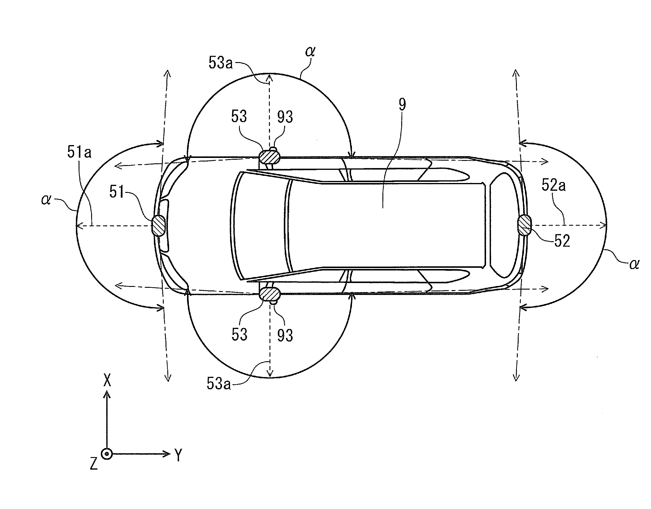
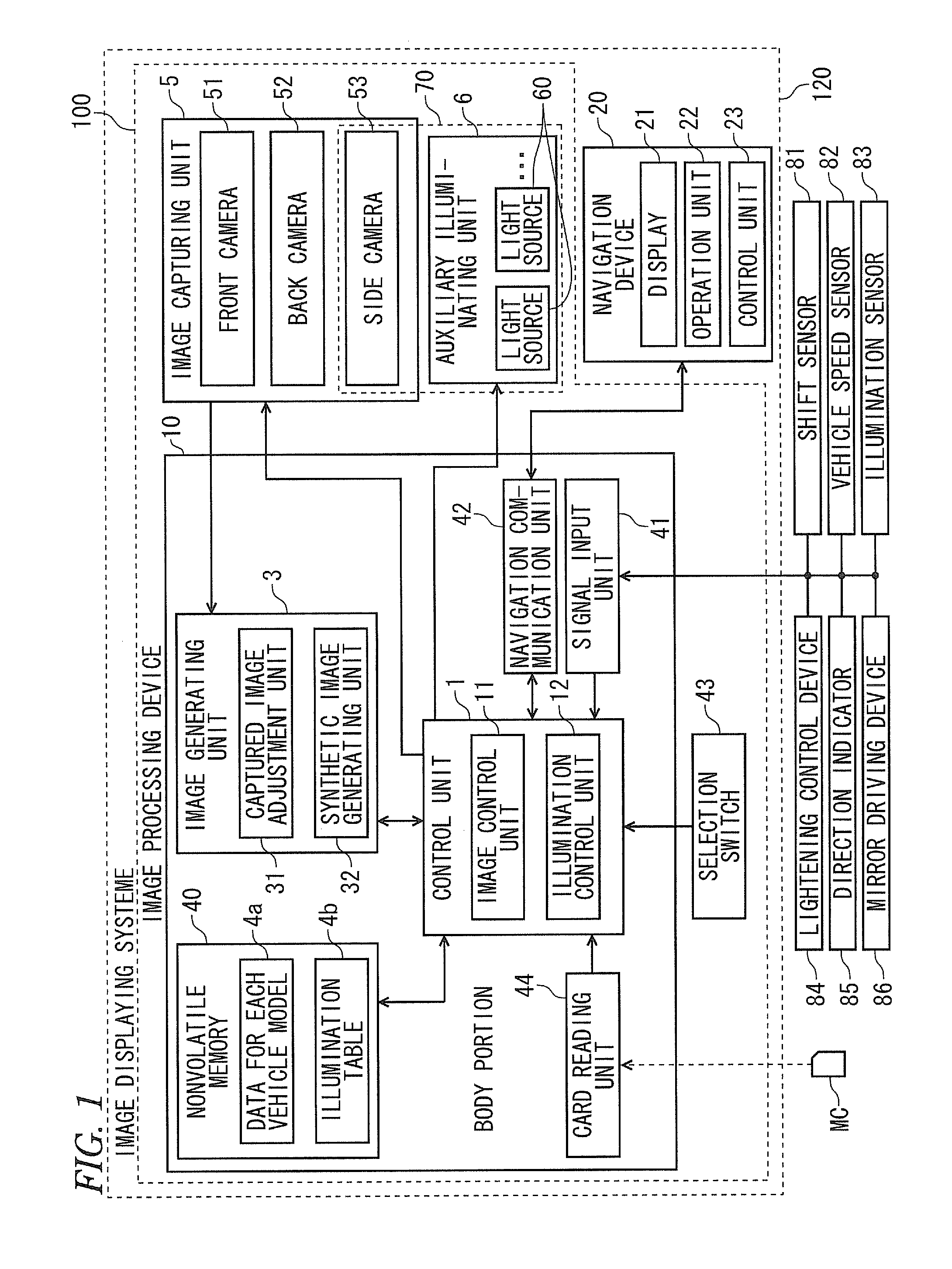
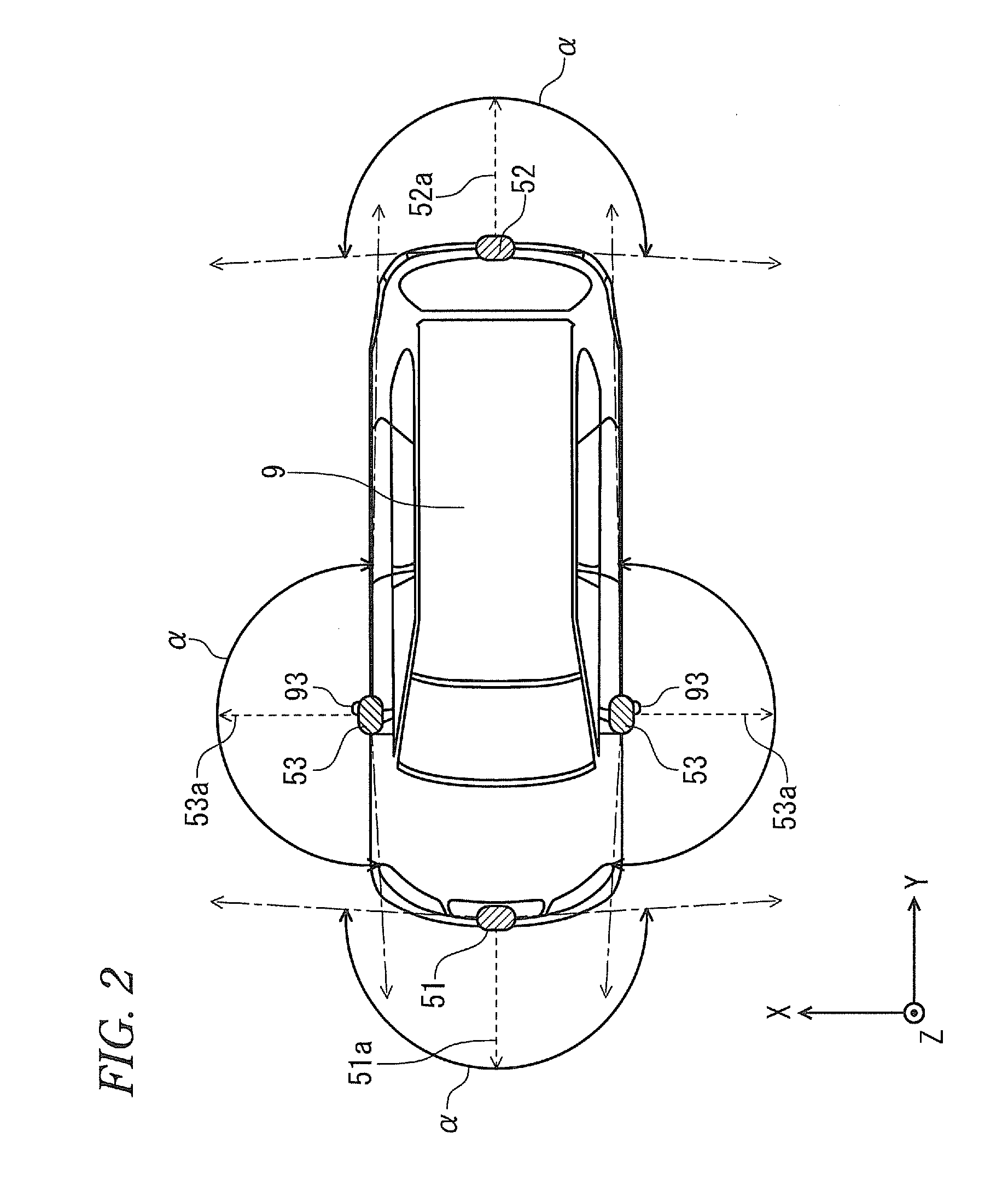
[0058]FIG. 1 is a block diagram illustrating the configuration of an image displaying system 120 according to a first embodiment. This image displaying system 120 is installed in a vehicle (in an embodiment of the present invention, a car), and has a function of generating an image through capturing images of a periphery of a vehicle and displaying the generated image in a cabin. A user (representatively, a driver) of the image displaying system 120 can grasp the appearance of the periphery of the vehicle substantially in real time by using the image displaying system 120.

[0059]As illustrated in FIG. 1, the image displaying system 120 mainly includes an image processing device 100 configured to generate peripheral images showing the periphery of the vehicle, and a navigation device 20 configured to display various kinds of information to a user in the vehicle. The peripheral images generated by the image processing device 100 are displayed on the navigation ...

second embodiment

2. Second Embodiment

[0176]Then, a second embodiment will be described. Since the configuration and processing of the image displaying system according to the second embodiment are almost the same as those according to the first embodiment, but only a part thereof differs from that according to the first embodiment, the differences between the embodiments will be described hereinafter.

[0177]In the vehicle confirmation mode M22 according to the second embodiment, in response to the driver's operation of a turn signal switch of a direction indicator 85, the viewpoint position of the virtual viewpoint VP of the synthetic image FP4 is moved.

[0178]FIG. 18 is a view illustrating a state transition of a screen in a vehicle confirmation mode, and FIG. 19 is a view illustrating a transition of positions of virtual viewpoints. If the turn signal input from the direction indicator 85 is in an off state, that is, if there is no direction indication, the viewpoint position of the virtual viewpoin...

third embodiment

3. Third Embodiment

[0190]Then, a third embodiment will be described. Since the configuration and processing of the image displaying system according to the third embodiment are almost the same as those according to the first embodiment, but only a part thereof differs from that according to the first embodiment, the differences between the embodiments will be described hereinafter.

[0191]The three light sources 60 arranged in one side camera unit 70, as shown in FIG. 6, illuminate the front area FA, the center area CA, and the rear area BA. Among them, it is possible to illuminate the front area FA through the headlights provided in the vehicle 9 as the standard.

[0192]FIG. 21 is a view illustrating an area that can be illuminated by the headlights 98 of the vehicle 9. In the drawing, an area HA, which can be illuminated to the extent that an image with sufficient brightness (for example, 0.5 lux or more) can be acquired by the headlights 98, is indicated as hatched area. Accordingly,...


PUM


Abstract

A plurality of light sources to assist in image capturing is attached to a vehicle at low cost and simplicity. Three light sources that illuminate a side area in the same direction of the vehicle are fixed to and accommodated in the same housing in a state where light axes of the light sources are directed to different directions from each other. Through this, the three light sources are integrated into a side camera unit by the housing. Accordingly, by attaching the side camera unit only, the light sources can be attached to the vehicle at a time. As a result, the light sources for widely illuminating the side area of the vehicle can be mounted on the vehicle at low cost and simplicity.

Description

TECHNICAL FIELD[0001]The present invention relates to a technology to perform an illumination to assist in capturing images of the periphery of a vehicle.BACKGROUND ART[0002]In the related art, an image displaying system has been known, which is installed on a vehicle such as an automobile to display images obtained by capturing the images of the periphery of the vehicle through vehicle cameras on a display provided in a cabin. By using this image displaying system, a driver can grasp the state of the periphery of the vehicle almost in real time.[0003]For example, an outer area of a front fender that is the opposite side to a driver's seat is liable to be in the dead angle, and thus it is difficult for a driver to grasp the clearance between a vehicle body and an obstacle. By contrast, if the image displaying system is used, images showing the outer area of the front fender are acquired by capturing the images through vehicle cameras, and the acquired images are displayed on the dis...

Claims


Application Information

Patent Timeline
IPC IPC(8): B60Q1/00H04N5/225H04N7/18
CPCB60Q1/2665B60Q1/32B60R1/00B60R2300/103B60R2300/8093B60R2300/303B60R2300/607B60R2300/806B60R2300/105B60R1/30B60R1/23
Inventor YAMADA, MASAHIRO
Owner FUJITSU GENERAL LTD
Learn More