Mirror for use in a microlithography projection exposure apparatus

a microlithography and exposure apparatus technology, applied in the direction of mirrors, printers, instruments, etc., can solve the problems of reducing the intensity of reflected radiation, and achieve the effect of efficient and rapid production of surface correction and no significant impairment of reflectivity of mirrors

a microlithography and exposure apparatus technology, applied in the direction of mirrors, printers, instruments, etc., can solve the problems of reducing the intensity of reflected radiation, and achieve the effect of efficient and rapid production of surface correction and no significant impairment of reflectivity of mirrors

US20120229784A1Active Publication Date: 2012-09-13CARL ZEISS SMT GMBH

Image

  • Mirror for use in a microlithography projection exposure apparatus
  • Mirror for use in a microlithography projection exposure apparatus
  • Mirror for use in a microlithography projection exposure apparatus

Examples


Embodiment Construction

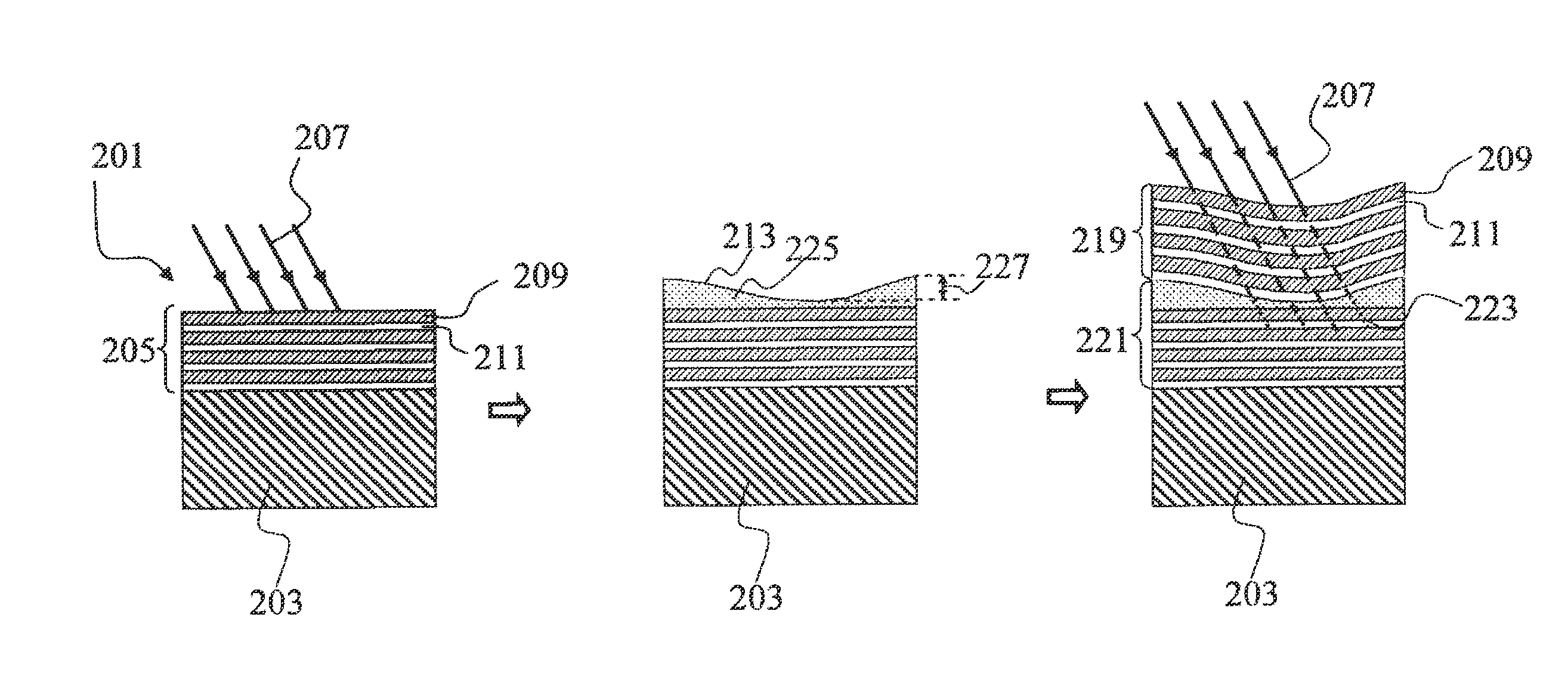
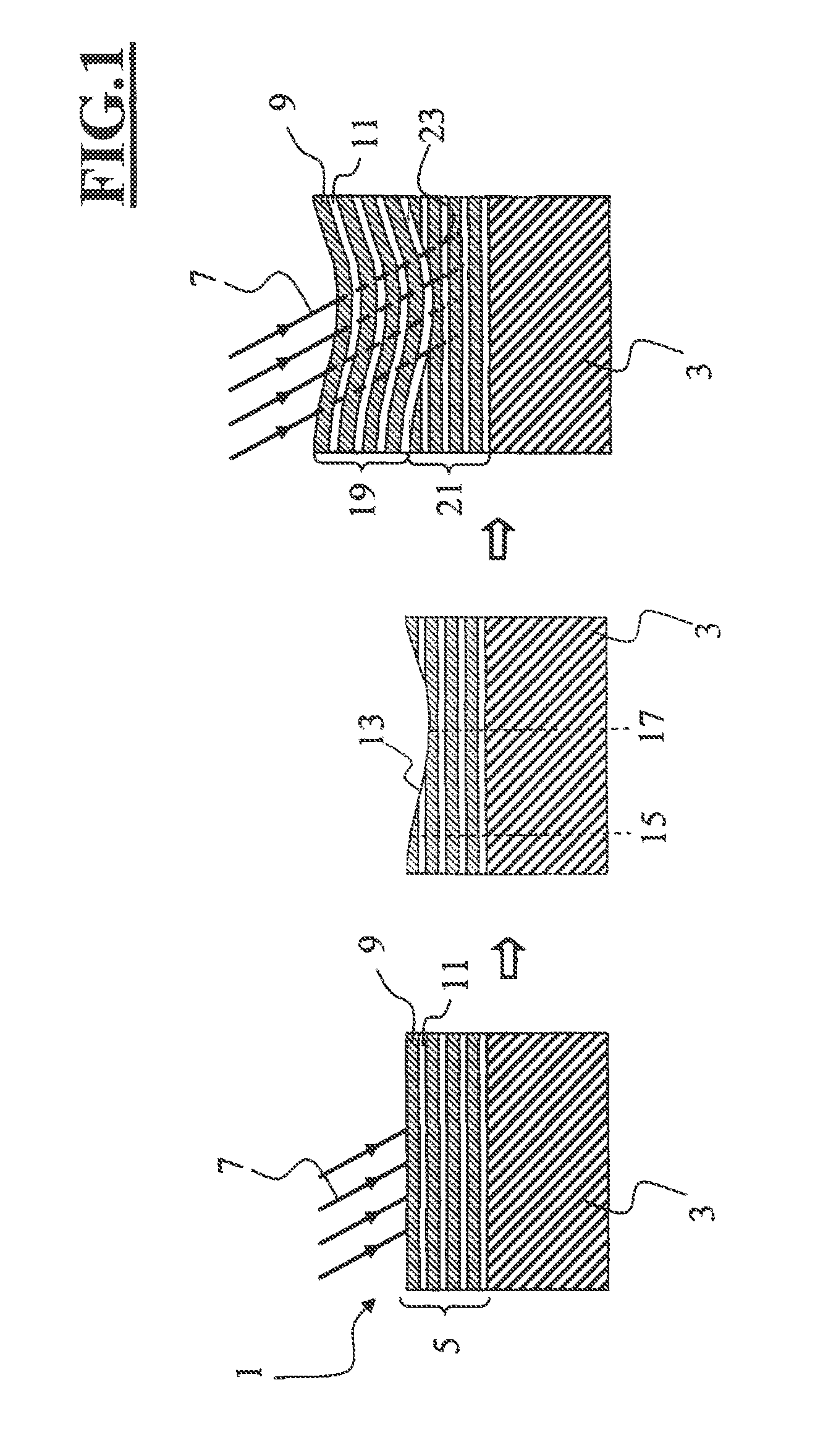
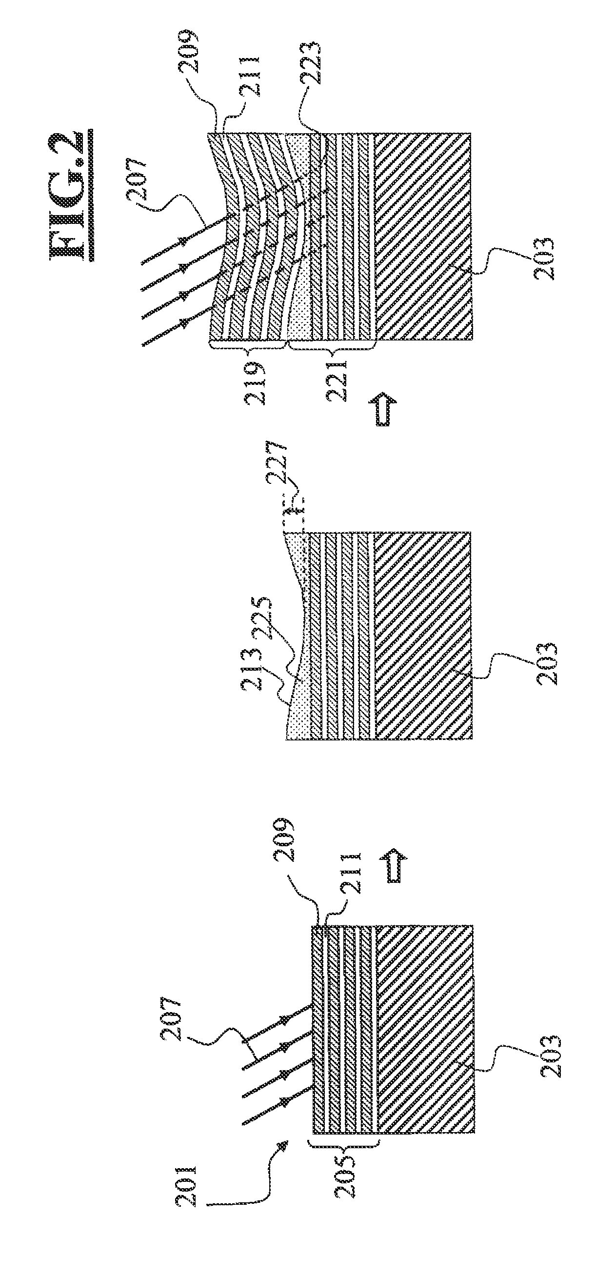
[0044]The reference signs have been chosen such that objects illustrated in FIG. 1 have been provided with single-digit or two-digit numerals. The objects illustrated in the further figures have reference signs having three and more digits, wherein the last two digits indicate the object and the preceding digits indicate the number of the figure in which the object is illustrated. The reference numerals of identical objects illustrated in a plurality of figures therefore correspond in terms of the last two digits. By way of example, the reference signs 3, 203 and 303 identify the mirror substrate in FIGS. 1, 2 and 3.

[0045]FIG. 1 shows, on the left-hand side, an embodiment of a mirror for use in a microlithography projection exposure apparatus in an initial state before correction of the surface form. The mirror 1 comprises a substrate 3 and a group of layers 5. In the present case, the substrate 3 consists of SiO2 (quartz). The group of layers 5 comprises a plurality of individual l...


PUM


Abstract

A mirror including a substrate and a reflective coating that includes a first group of layers and a second group of layers arranged between the substrate and the first group of layers. Both the first and second groups of layers include a plurality of alternating first material layers and second material layers, arranged one above another. The refractive index of the first material for radiation in the range of 5-30 nm is greater than the refractive index of the second material in that wavelength range. The first group of layers is configured to have a number of layers that is greater than 20, such that, upon irradiation with radiation having a wavelength in the range of 5-30 nm, less than 20% of the radiation reaches the second group of layers, which has a layer thickness variation for correcting the surface form of the mirror.

Description

CROSS REFERENCE TO RELATED APPLICATIONS[0001]This is a Continuation of International Application No. PCT / EP2010 / 062426, with an international filing date of Aug. 26, 2010, which was published under PCT Article 21(2) in English, and which claims priority to German Patent Application No. 10 2009 029 471.6, which was filed on Sep. 15, 2009. The entire contents of both the international and the German applications are hereby incorporated into the present application by reference. FIELD OF AND BACKGROUND OF THE INVENTION[0002]The present invention relates to a mirror for use in a microlithography projection exposure apparatus comprising a substrate and a reflective coating, a projection objective for use in a microlithography projection exposure apparatus, a microlithography projection exposure apparatus, and also a method for the correction of a surface form of a mirror comprising a substrate and a reflective coating.[0003]Microlithography projection exposure apparatuses serve for produ...

Claims


Application Information

Patent Timeline
13 Sep 2012
Publication
US20120229784A1
IPC
G03B27/72
CPC
G02B5/0833; G03F7/70958; G03F7/70316; G03F7/20; G02B5/08; G03F7/70308; G03F7/70191
Inventors
ROCKTAESCHEL, MARTIN; ENKISCH, HARTMUT