Magneto-resistance effect element, magnetic head, magnetic recording device and magnetic memory

Inactive Publication Date: 2012-06-12
KK TOSHIBA
View PDF29 Cites 1 Cited by
  • Summary
  • Abstract
  • Description
  • Claims
  • Application Information

AI Technical Summary

Benefits of technology

[0016]Since the spacer layer is made of the oxide, nitride and the like as described above, the magnetization of the spacer layer is relatively small. Therefore, the magnetic control of the spacer can be carried out by a relatively small external magnetic field, different from the free layer of the conventional SV film and the like. In this case, the magnetic domain of the spacer layer can be rendered a single magnetic domain. As a result, some magnetic noise such as Barkhausen noise can be effectively prevented.
[0019]Generally, in order to enhance the change in resistance of a magneto-resistance effect element, that is, the MR effect thereof, it is required to maintain the spin information from the magnetic layer (pinned layer). In the magneto-resistance effect element according to the aspects of the present invention, therefore, since the spin information can be maintained in the spacer layer, the magneto-resistance effect element can exhibit a larger MR effect even though the spacer layer has a magnetization as large as the free layer of the conventional SV film.
[0020]In the first magneto-resistance effect element, the current bias generating portion conducts the magnetic domain control of the spacer layer by the bias magnetic field, and preferably renders the magnetic domain of the spacer layer a singe magnetic domain. As a result, some magnetic noise such as Barkhausen noise can be effectively prevented.

Problems solved by technology

In this point of view, it is difficult to render the magnetic domain of the spacer layer the single magnetic domain so that some magnetic noise such as Barkhausen noise maybe caused.

Method used


Image

  • Magneto-resistance effect element, magnetic head, magnetic recording device and magnetic memory
  • Magneto-resistance effect element, magnetic head, magnetic recording device and magnetic memory
  • Magneto-resistance effect element, magnetic head, magnetic recording device and magnetic memory

Examples


first embodiment

( First Magneto-Resistance Effect Element)

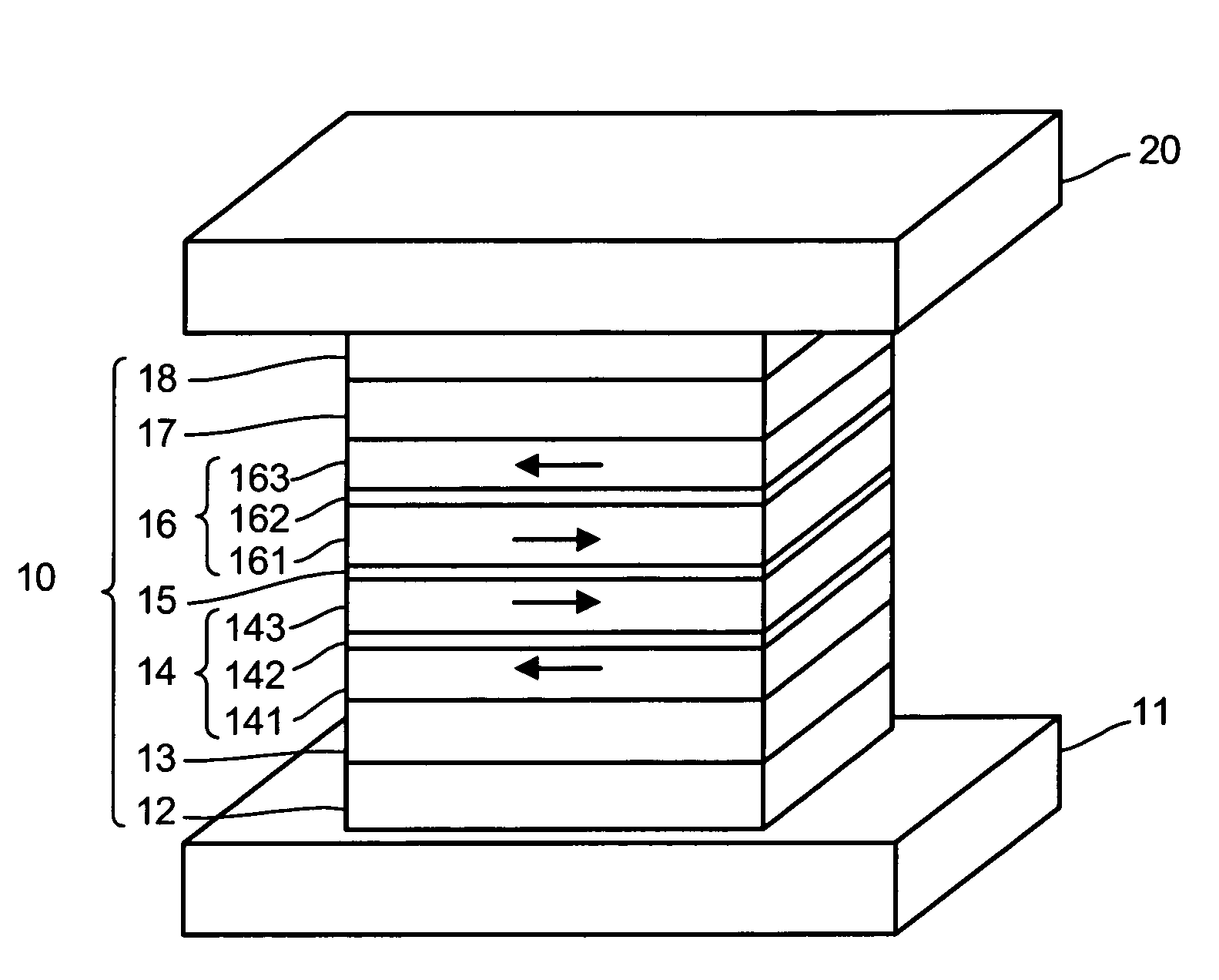
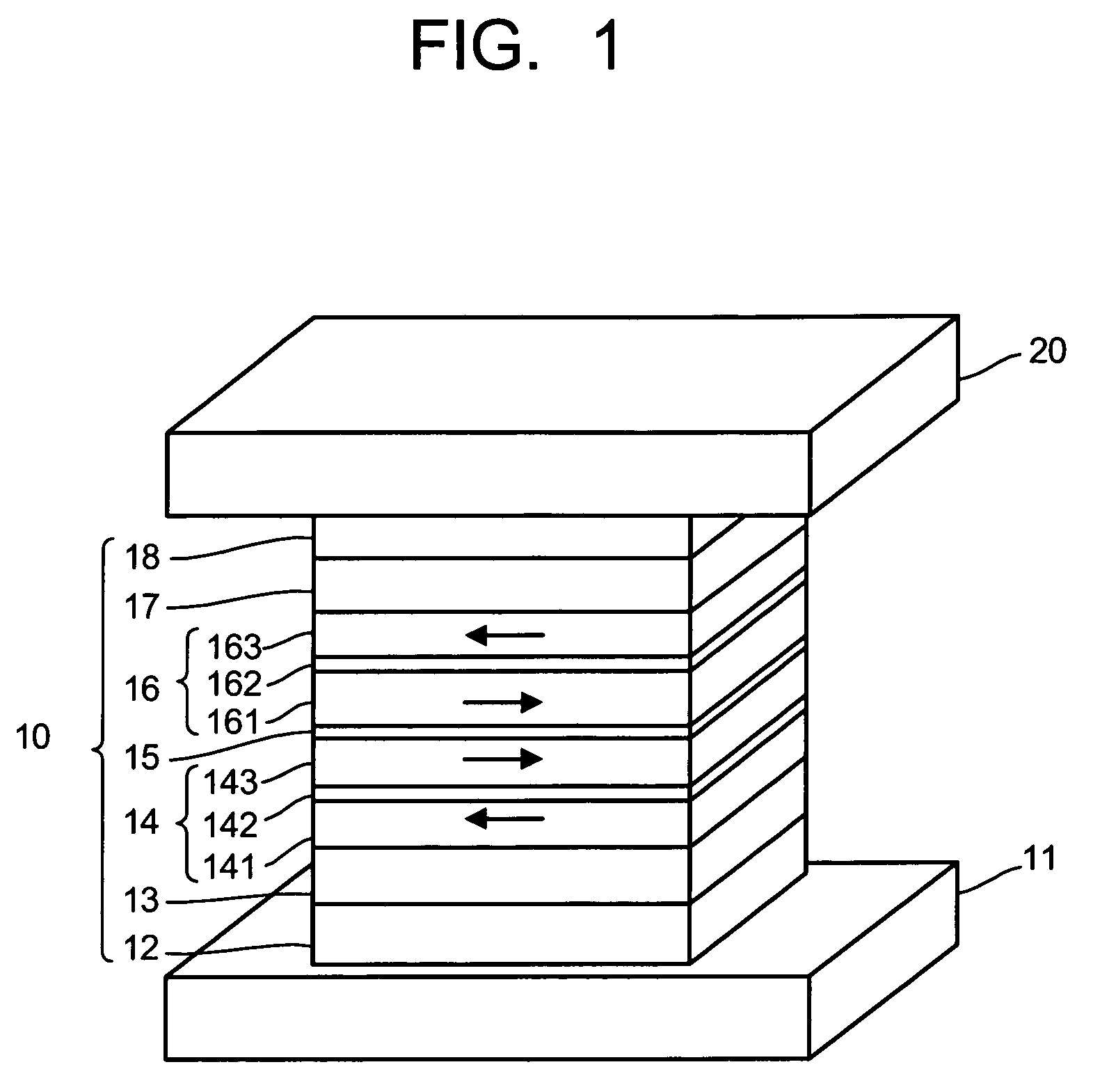
[0061]FIGS. 4 to 6 relate to the concrete structure of the magneto-resistance effect element wherein a current bias generating portion 21 is provided for the above-described magneto-resistance effect element as a fundamental structure. In these drawings, for simplification, the bottom electrode 11 and the top electrode 20 are omitted so that only the MR film 10 is represented as the magneto-resistance effect element. Since the current bias generating portion 21 applies a magnetic field to the spacer layer 15, the spacer layer 15 is concretely depicted in the MR film 10.

[0062]As shown in FIGS. 4 to 6, the current bias generating portion 21 is formed as a platy structure. In FIG. 4, the current bias generating portion 21 (platy structure) is disposed adjacent to the side surface of the magneto-resistance effect element so that the current is flowed therein along the thickness direction (from the top side to the bottom side). In this case, the ...

example 1

[0081]Example 1 relating to the magneto-resistance effect element as shown in FIG. 4 (7) will be described. In Example 1, the magneto-resistance effect element was formed as follows:

[0082]Bottom electrode 11: NiFe 1.5 μm

[0083]Underlayer 12 (buffer layer 12a / seed layer 12b): Ta 5 nm / Ru 2 μm

[0084]Pinning layer 13: PtMn 15 nm

[0085]Pinned layer 14 (pinned layer 141 / magnetic coupling layer 142 / pinned layer 143): CoFe 3 nm / Ru 0.9 nm / CoFe 3 nm

[0086]Spacer layer 15: TiOx 2 nm

[0087]Pinned layer 16 (pinned layer 161 / magnetic coupling layer 162 / pinned layer 163): CoFe 3 nm / Ru 0.9 nm / CoFe 3 nm

[0088]Pinning layer 17: PtMn 15 nm

[0089]Cap layer 18: Ta 5 nm

[0090]Current bias generating portion 21: Ti 50 nm

[0091]The above-described layers were subsequently formed except the top electrode to form the laminated body, and then, thermally treated at 290° C. for four hours under a magnetic field of 10 kOe so as to enhance the crystallinity of the laminated body and the regularization of the pinning layer...


PUM

PropertyMeasurementUnit
thicknessaaaaaaaaaa
thicknessaaaaaaaaaa
thicknessaaaaaaaaaa

Abstract

A magneto-resistance effect element includes: a first magnetic layer of which a first magnetization is fixed in one direction; a second magnetic layer of which a second magnetization is fixed in one direction; a spacer layer located between the first magnetic layer and the second magnetic layer and made of at least one selected from the group consisting of an oxide, a nitride, an oxynitride and a metal; and a current bias generating portion, which is located adjacent to the spacer layer, for applying a bias magnetic field to the spacer layer.

Description

CROSS-REFERENCE TO RELATED APPLICATIONS[0001]This application is based upon and claims the benefit of priority from the prior Japanese Patent Application No. 2007-082013, filed on Mar. 27, 2007; the entire contents of which are incorporated herein by reference.BACKGROUND OF THE INVENTION[0002]1. Field of the Invention[0003]The present invention relates to a magneto-resistance effect element which is configured such that a sense current is flowed in the direction perpendicular to the film surface thereof. The present invention also relates to a magnetic head, a magnetic recording device and a magnetic memory which utilize the magneto-resistance effect element according to the present invention.[0004]2. Description of the Related Art[0005]Recently, the performance of a magnetic device, particularly such as a magnetic head is enhanced by means of Giant Magneto-Resistance Effect (GMR) made of a multilayered magnetic structure. Particularly, since a spin valve film (SV film) can exhibit ...

Claims


Application Information

Patent Timeline
Patent Type & Authority Patents(United States)
IPC IPC(8): G11B5/39
CPCB82Y25/00G01R33/093G11B5/3932G11C11/16H01F10/3254H01L43/08H01F10/3272H10N50/10
Inventor ITO, JUNICHIFUKUZAWA, HIDEAKIYUASA, HIROMIFUJI, YOSHIHIRO
Owner KK TOSHIBA
Why Eureka
Try Eureka