Intermediate floor for a radial turbine engine

a technology of radial turbine engine and intermediate floor, which is applied in the direction of engine starters, liquid fuel engines, separation processes, etc., can solve the problems of short maintenance cycle of radial turbocompressors, damage to components, and insufficient purity of partial gas streams, so as to improve the purity of consumption gas, improve the quality of consumption gas, and improve the effect of gas consumption

Inactive Publication Date: 2012-09-13
SIEMENS AG
View PDF2 Cites 21 Cited by
  • Summary
  • Abstract
  • Description
  • Claims
  • Application Information

AI Technical Summary

Benefits of technology

[0010]According to one embodiment of the invention, the consumption-gas removal channel opens into the deflecting channel in the region of the transition between the first outer surface section and the third outer surface section. In this embodiment, the consumption gas can advantageously be removed in a particularly effective manner as a low-particulate gas of the main flow from said main flow through the consumption-gas removal channel Advantageous use is made of the fact that the process gas flow has already been deflected by a large deflection angle in the vicinity of the return flow channel during operation, with the result that a particularly small amount of solid or liquid particles comes into the vicinity of the mouth of the consumption-gas removal channel since the solid or liquid particles cannot completely follow the deflection of the gas flow. Another advantage is that if the diaphragm is used in a radial turbomachine with a vertical axis of rotation and with a main flow direction running from the top down, the solid or liquid particles move away from the mouth of the consumption-gas removal channel or do not reach the mouth owing to the force of gravity, and this improves the purity of the consumption gas.
[0011]The consumption-gas removal channel preferably runs in the diaphragm in a plane in which the axis of the diaphragm is situated. Moreover, the consumption-gas removal channel is arranged relative to the axis of the diaphragm so as to slope toward the third outer surface section. If the diaphragm is installed in the radial turbomachine with a vertical axis of rotation in this embodiment, the slope of the consumption-gas removal channel advantageously contributes to fe...

Problems solved by technology

However, among the disadvantages of removing the partial gas stream from the main flow is that, in many cases, the quality of the partial gas stream is inadequate in terms of purity requirements since the partial gas strea...

Method used


Image

  • Intermediate floor for a radial turbine engine
  • Intermediate floor for a radial turbine engine

Examples


Embodiment Construction

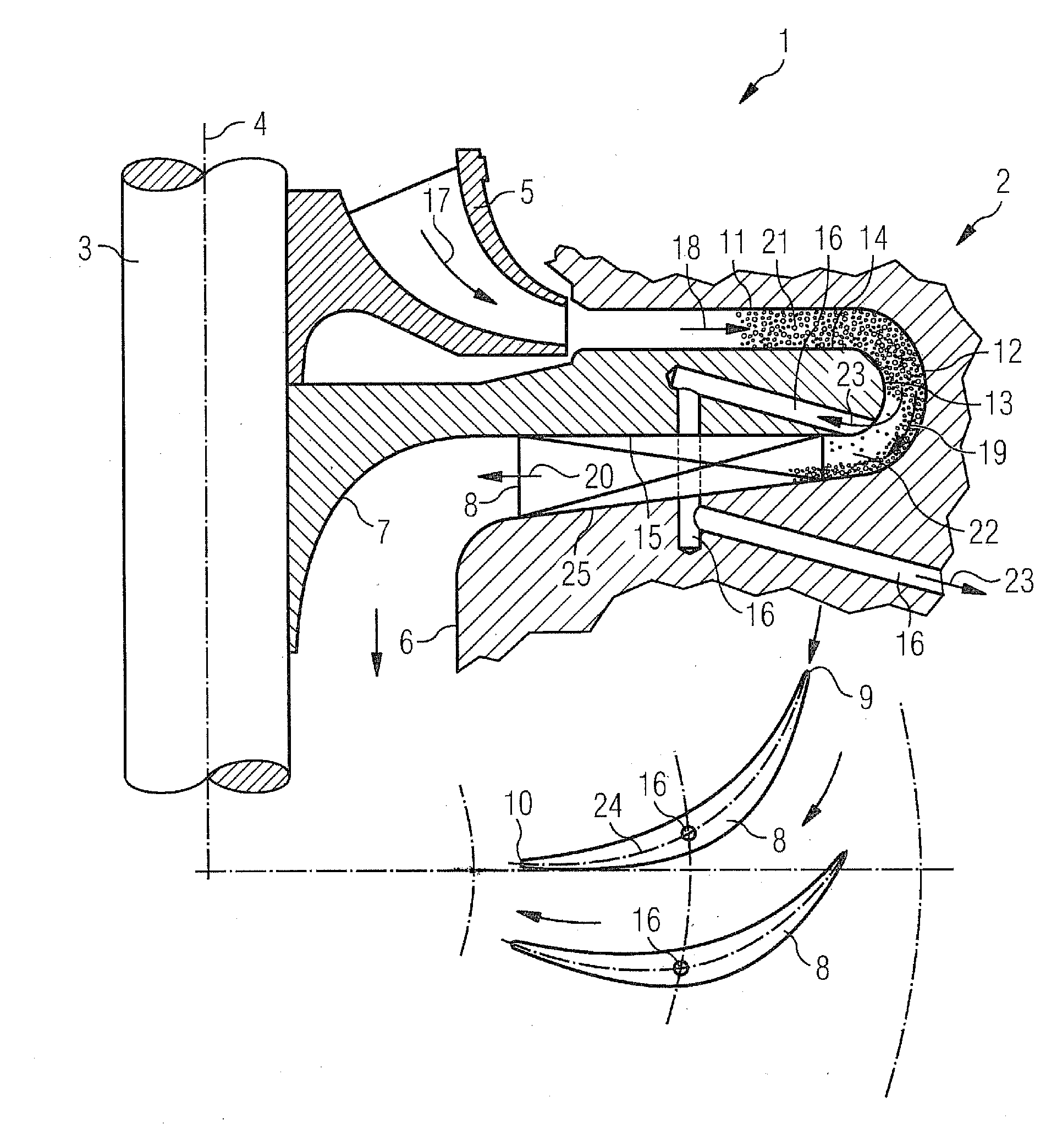
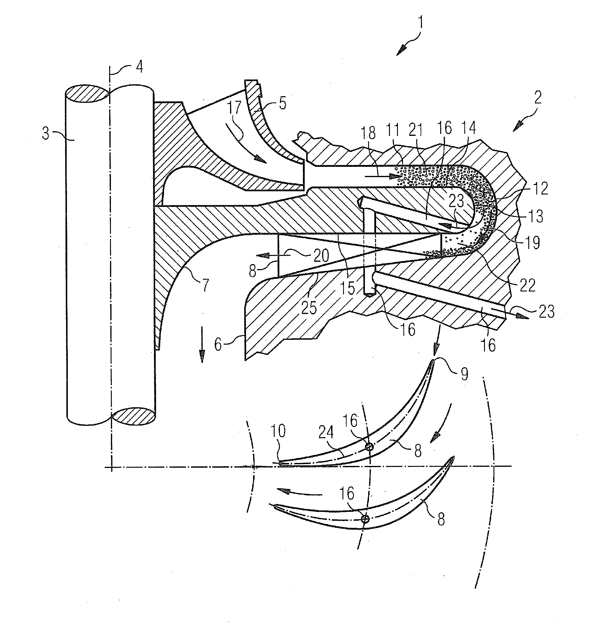
[0017]In FIG. 1, a radial compressor stage 2 of a radial compressor 1 according to the invention in accordance with one illustrative embodiment of the invention is shown schematically, wherein the radial compressor stage 2 has the diaphragm 7 according to the invention. Schematic sectional views of guide vanes 8 of the radial compressor stage 2 are furthermore shown. The radial compressor 1 shown in FIG. 1 has an inner casing 6, in which is arranged a radial compressor impeller 5, which is seated on a shaft 3 and is driven by the latter. By means of the radial compressor impeller 5, the process gas is deflected radially outward. The direction of the main flow 17 in the radial compressor impeller 5 is indicated by an arrow in FIG. 1. A radial diffuser channel 11, a deflecting channel 12 and a return flow channel 25 furthermore connect to the radial compressor impeller 5 on the downstream side. The main flow 18 in the radial diffuser channel 11, the main flow 19 in the deflecting chan...


PUM

PropertyMeasurementUnit
Thicknessaaaaaaaaaa

Abstract

A radial turbomachine includes a radial diffuser channel with a diaphragm, a deflecting channel connecting to the radial diffuser channel downstream thereof, and a return flow channel connecting to the deflecting channel downstream thereof. The main flow direction of the radial diffuser channel runs radially from inside to outside. The main flow direction of the deflecting channel is deflected from radially outward to radially inward. The main flow direction of the return channel runs radially from outside to inside. The diaphragm comprises first, second and third outer surface sections. The first outer surface section has a convex shape for delimiting the deflecting channel. At least one consumption-gas removal channel is provided in the diaphragm so that, if the main flow in the deflecting channel comprises solid or liquid particles, a consumption gas can be discharged therefrom through the consumption-gas removal channel as low-particulate gas of a main flow.

Description

CROSS REFERENCE TO RELATED APPLICATIONS[0001]This application is the U.S. National Stage of International Application No. PCT / EP2010 / 067174, filed Oct. 11, 2010, and claims the benefit thereof. The International Application claims the benefits of German application No. 10 2009 052 619.6 DE filed Oct. 11, 2009. All of the applications are incorporated by reference herein in their entirety.FIELD OF INVENTION[0002]The invention relates to a radial turbomachine having a radial diffuser channel with a diaphragm, the main flow direction through which runs radially from the inside outward, a deflecting channel, which connects to the radial diffuser channel downstream thereof and the main flow direction through which is deflected from radially outward to radially inward, and a return flow channel, which connects to the deflecting channel downstream thereof and the main flow direction through which runs radially from the outside inward, wherein the diaphragm has a first outer surface section...

Claims


Application Information

Patent Timeline
IPC IPC(8): F04D7/04F04D29/44B01D45/06F04D31/00
CPCB01D45/06F04D31/00F04D29/441F04D7/04F05D2250/52
Inventor JONEN, WERNERROBENS, PETER
Owner SIEMENS AG
Why Eureka
Try Eureka