

Ophthalmosurgical Measuring Device
a measuring device and ophthalmosurgical technology, applied in the field of ophthalmosurgical measuring devices, can solve the problems of not being able to detect the relative pressure in the aspiration line or the irrigation line, and achieve the effect of detecting even more quickly
- Summary
- Abstract
- Description
- Claims
- Application Information
AI Technical Summary
Benefits of technology
Problems solved by technology
Method used
Image

Examples
Embodiment Construction
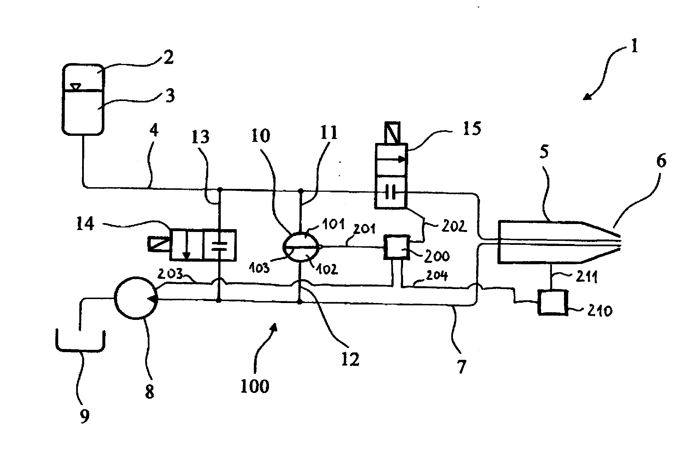
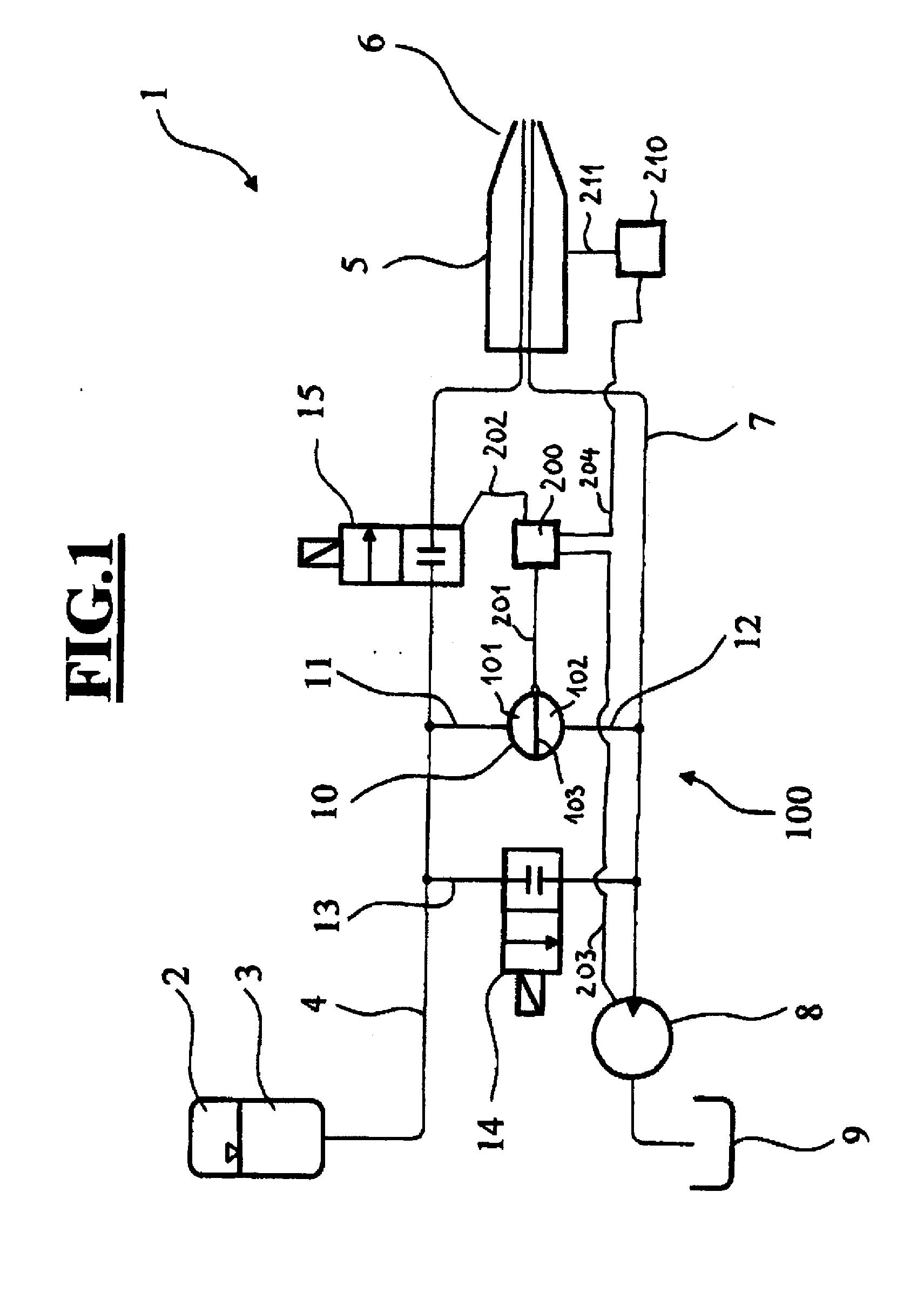
[0025]FIG. 1 is a schematic of an embodiment of the ophthalmosurgical system 1 according to the invention. An irrigation fluid container 2 contains an irrigation fluid 3 that can flow through an irrigation line 4 to a handpiece 5 having a tip 6. The tip 6 is designed in such a way that it is able, with the aid of a needle set in vibration by ultrasound, to break up a clouded and relatively hard lens of an eye into small fragments. The fluid located in the anterior chamber of the eye and the fragmented particles are guided through an aspiration line 7 to a suction pump 8, which discharges the fluid and the particles into a container 9. A sensor 10 is arranged between the irrigation line 4 and the aspiration line 7.
[0026]In this embodiment, the sensor is connected by way of a first line 11 to the irrigation line 4, and by way of a second line 12 to the aspiration line 7. It is thus possible for the sensor to detect a differential pressure between the irrigation line 4 and the aspirati...
PUM
 Abstract
Description
Claims
Application Information